


CARF Galloping Ghost build
 02-10-2018, 11:32 AM
#51

I have a 750cc fuel tank. So I installed a 2l coke bottle in the back. The bottle is connected with a T to the overflow line from the fuel tank. After refilling the tank a close the overflow line and pump up the bottle to 0.3bars. And this takes care for constant flow while flying.
 02-10-2018, 04:01 PM
#52

Thread Starter

Fantastic. I totally get it. Here's why I'm interested. Did you have to lean the engine at all after adding this? Or does is just keep an even flow. Usually when adding a fuel pump, the engine runs a little richer, so have to lean it out. With the CARF Ghost, once the engine is installed, I really can't get to the needles for the the carburetors. unless pulling the engine. I need to figure that out. three carbs = 3 sets of high-low needles.
02-10-2018, 10:21 PM
#53
We installed the system on Simon’s Pitts at Joe Nall. Very easy to handle and very save.
On his Spitfire we didn’t have enough space for a bottle. So we installed the fuel pump. It died at takeoff and I made a deadstick landing faaaaaaar away. Think there is a video on YouTube
to adjust the carbs is needed on the first flights. L you can adjust in flight. But H you need to fly because the engine reaches rpm’s you can’t get on ground. On Voodoo I remove the red covers from the needles so I can get them with a pointed pliers to set H correct. Most time it sounds perfect on ground, but I too rich on flight.
Out team-pilot Simon wrote a good discription in correct English in the thread “all about kolm engines”
The pressure bottle i fill up with a blood pressure device. Normal tools doesn’t have a scale which is fine enough.
02-11-2018, 12:05 PM
#54
Thread Starter
Test fit the engine again to get the exhaust tubes to fit out the bottom. Took several times to get the holes aligned. Now that they're centered, I just need a little more trimming. Used hysol to mount the engine front support bracket to the lower cowl. All seems to align nice with the spinner. Need to install throttle & choke servos on the other side of the firewall.
02-16-2018, 07:23 AM
#56
Thread Starter
I was just going to mount and test the engine in the air frame, but decided to build a test stand. Since the needles are difficult to get to, it made more sense to test run first and think a little on how to get access to them once the engine is mounted. I'm going to see if I can add some sort of channel to each set of needles that I can access outside the air frame. This trouble is on the carb closest to the firewall. The next two carb I should be able to access a little easier.
02-16-2018, 08:47 AM
#57

Join Date: Jan 2018
Posts: 4
Likes: 0
Received 0 Likes
on
0 Posts
Test fit the engine again to get the exhaust tubes to fit out the bottom. Took several times to get the holes aligned. Now that they're centered, I just need a little more trimming. Used hysol to mount the engine front support bracket to the lower cowl. All seems to align nice with the spinner. Need to install throttle & choke servos on the other side of the firewall.
Robert the build is looking great your posts are a great help to the build we have going on here, thanks for all the great pictures. Would you mind giving the measurements for the holes you drilled for the exhaust. Thanks
Todd
02-16-2018, 10:17 AM
#58
Thread Starter
Hi Todd... No problem. Just an FYI, my holes were estimated based on the IL-230 and the using the Kolm aluminium standoff's for the engine mount. Also, if you notice, the exhausts come out at an angle and not straight down. So, you have to slide the engine in from the front and slide at an angle towards the back a little. It doesn't drop in straight down. I tried to get measurements as close to the center of the holes that I could. Obviously I would make small holes and trial fit from there. But, it looks like from the bottom/outside of the cowl, the holes seem to be aligned about 0.5" of the center line seam of the fuse. Pictures attached. Then from inside the cowl, the first hole looks to be about 3.5" from the firewall, and then they appear to be evenly spaced at about 3" apart. so, from first hole to second is 3" and second to third about 3".. so... first hole center to third hole center 6". Rob
Last edited by rbgetz; 02-16-2018 at 12:24 PM.
02-16-2018, 12:18 PM
#59
Thread Starter
One more point, my engine was mounted not only with the Kolm aluminium stand-off but also the phenolic washer that was supplied with the CARF Engine installation kit. See picture. So the total stand-off length is slightly longer then the just aluminium stand-off. This should help you get really close.
Rob
Rob
02-18-2018, 05:31 AM
#61
Thread Starter
Hi Tom,
I was thinking about that as well. they are fairly small now, but the issue I had is if they are any smaller, it will be hard to drop the engine in. Good point and I'll have to see what I can do as not to lose cooling.
Rob
I was thinking about that as well. they are fairly small now, but the issue I had is if they are any smaller, it will be hard to drop the engine in. Good point and I'll have to see what I can do as not to lose cooling.
Rob
02-20-2018, 04:49 PM
#63
Thread Starter
I'll be tightening the holes a little. but I'm still trying to figure out how I'll get access to the needles, and just as important, is access to the cylinder heads to take the caps off and make valve gap adjustments. The GG has the IL-230 extremely tight in the cowl. The only way you'd be able to make valve gap adjustments would be to remove the engine completely from the air frame. Not a simple task. I'm open for discussion on this, but I'd like clear access. I'm thinking designing an access panel. It might be tricky with baffles, air intake and front engine support bracket in place. Otherwise I'd just make the complete lower half of the cowl removable. So, anyone else working on the GG and a Kolm, I'd be interested in hearing your thoughts. I understand that once the engine has settled in, these types of adjustments are not made often.
02-20-2018, 11:18 PM
#64
this is how i did on voodoo
i want also to have acess to check the valve-gaps without pull out the engine. so i builded this hatch. the balles are cutted in this area. this is not a big problem.
i want also to have acess to check the valve-gaps without pull out the engine. so i builded this hatch. the balles are cutted in this area. this is not a big problem.
02-21-2018, 03:46 AM
#65
Thread Starter
ahh... excellent. I was looking at this last night and almost the same. I outlined in red in my photo to show where I was thinking of cutting. So, very similar. I'll probably cut it a little tighter then I show.
02-24-2018, 11:31 AM
#66
Thread Starter
OK... making progress. Now have full access to tuning needles and able to easily take of cylinder head covers off for valve-gap adjustments. I'm feeling much better now! I first glassed the inside with 2" west systems reinforcing tape just to give a little more support to the hatch. After I cut the hatch, I added about a 3mm-4mm reveal around the opening with thin G-10 strips. So it will seal up nice as not to affect the movement of air for cooling. thinking either round head 4/40 or even 2-56 round head screws or a countersunk flat head. It's also nice that I now have access to the throttle linkage in case of an issue.
Last edited by rbgetz; 02-24-2018 at 11:35 AM.
02-24-2018, 03:25 PM
#68
Thread Starter
I made some tab's for the hatch out of G-10. Then used blind-nuts and decided to go with 2-56 x 3/8" flat-head screws that I'll counter sink slightly. It will have a clean look on the outside with the screws set in. When the plane is upright, you really can't even see the hatch. I CA'd all tabs in place and then put a bead of hysol around everything once it was all lined up. Definitely open to see how others solved this. I'm also open to suggestions. Rob
 03-23-2018, 03:37 AM
#70
Thread Starter
Hi Dennis, Sorry, I'll post some updates soon. The weather improved here, up north, and was actually able to get some flights. And that "work" thing slowed me a bit. but have made some progress and really want to get the Ghost done soon.
rob
rob
03-24-2018, 12:00 PM
#72
Thread Starter
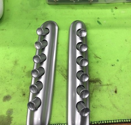
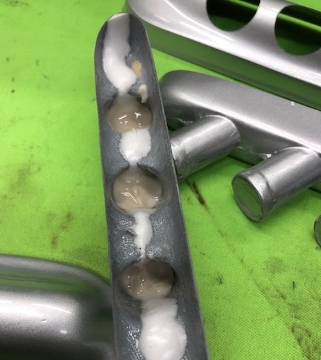
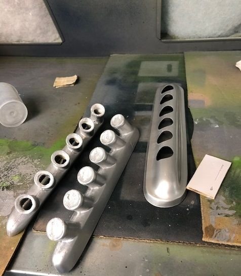
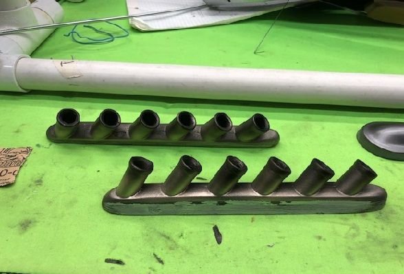
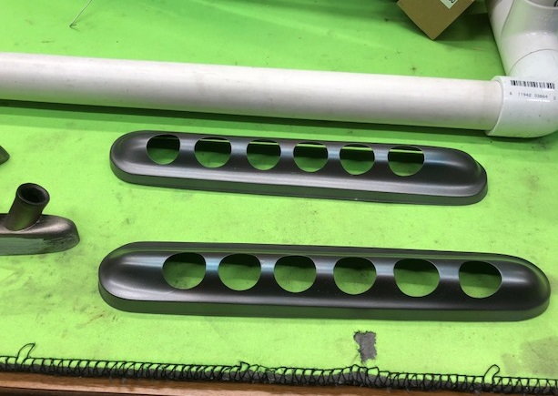
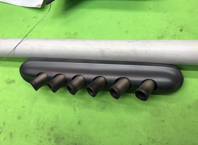
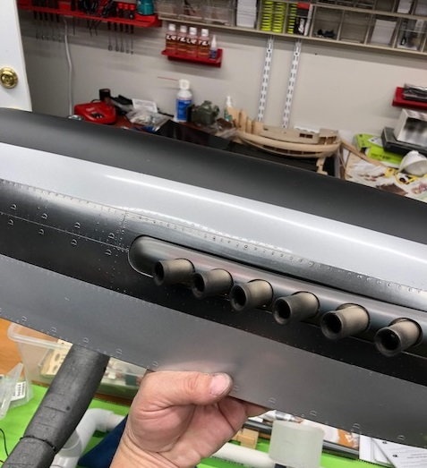
I'm not going to detail the plane too scale like, but I do want to add some panel weathering, a little airbrushing in areas, and just enough detail to highlight to the plane. The exhaust stacks that came with the kit are nice, just a little boring. So I thought I'd detail them a little. I cut each exhaust pipe open. The problem is they are so thin that I had to back fill each exhaust pipe with hysol before cutting them open. It made for a much more solid pipe in order to cut. Then weathered with my airbrush to give a little used look.
Last edited by rbgetz; 03-24-2018 at 12:06 PM.
03-24-2018, 01:04 PM
#73
Thread Starter
Here's a link to my test start of the IL-230. Before I install it in the plane I wanted to test. Since I'm added a fuel pump, I first wanted to ran it without the fuel pump connected. I then plan to hook the pump up test run, tune and do a final valve gap check before installing. I know when I added the same fuel pump to my Moki 300, I had to lean the carb a little. So just making sure it all works since this engine isn't easy to take in and out of the air frame. I couldn't go full throttle since I was by myself and couldn't hold the bench. You'll notice the stand starts moving even with a little throttle up.
03-25-2018, 01:44 PM
#74
Thread Starter
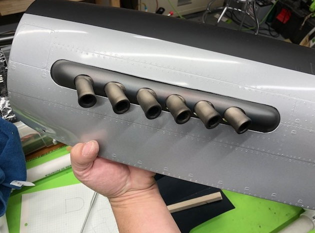
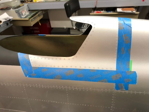
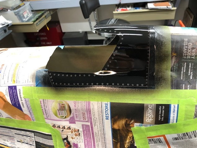
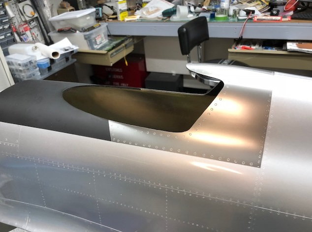
So I plan to highlight a few panels on the plane with a gloss aircraft aluminium color. I didn't want to go to a full chrome look. I painted the panel that is around the exhaust today. I'll probably then add a hot metal look to the aluminium panel in the area closer to the exhaust. I think it gives a better contrast to the exhaust and similar to the full scale.
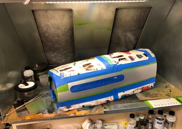
fine steel wool on in mold silver
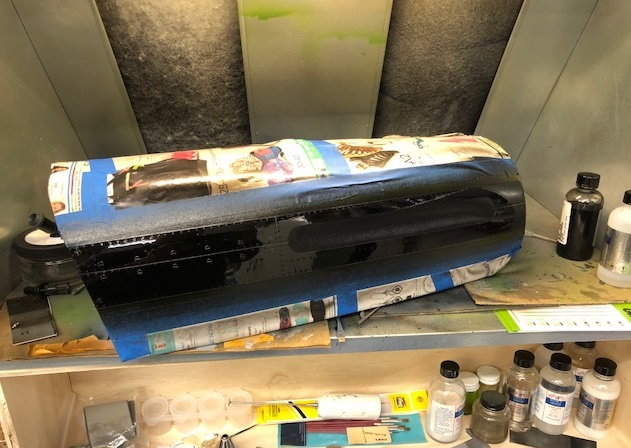
Gloss black under primer
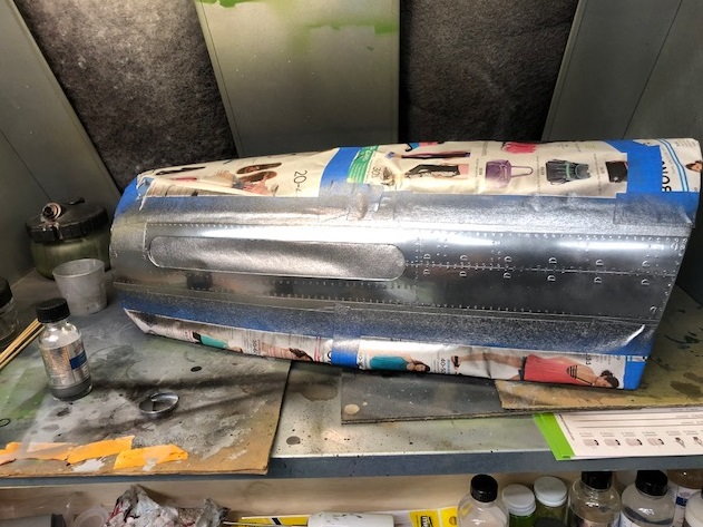
Alclad aircraft aluminium
Final clear coat to seal aluminium color.
fine steel wool on in mold silver
Gloss black under primer
Alclad aircraft aluminium
Final clear coat to seal aluminium color.
04-09-2018, 02:29 PM
#75
Thread Starter
Hey guys, sorry for more delay but caught influenza and been down for several days with high fever....and weather still really cold. But looks like things are improving on all fronts later in the week and I can get the engine test done and finally installed back in the plane. Here's a few pic of more detailing I'm doing. Again, not exactly like the full scale was, but gave more definition to the Canopy. CARF had no scale canopy defined so I had to create a few more rivets to outline where the full scale was. I just pushed a piece of small brass tubing over my old soldering iron. The one nice thing nice about a composite fuse, it is easy to melt in rivets. once you burn them in, I just sanded with a 1000 grit just to take off the the edges. primed and painted with Aircraft aluminium.
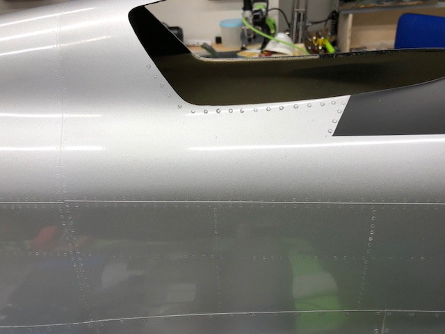
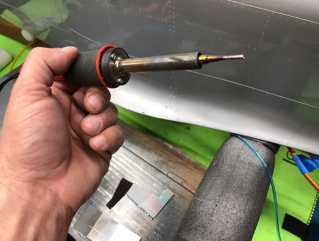
added brass tip to solder iron.
added brass tip to solder iron.