


Ziroli 92" p-47 build thread
 08-09-2019, 05:20 PM
#201
Routed wires/air hoses to center of wing and put Y extensions on ailerons and flaps and T's on air hoses.
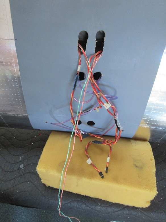
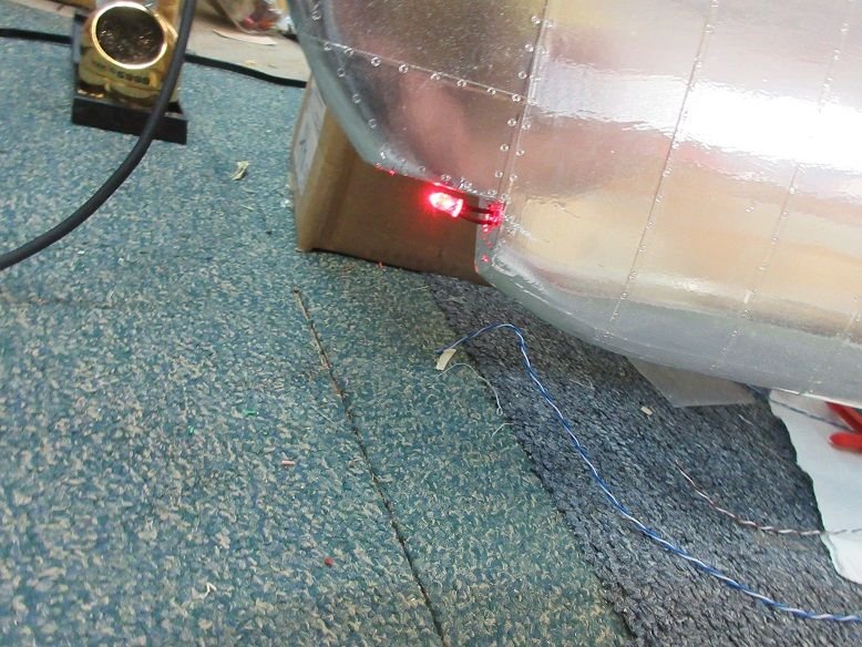
Landing light on left, underside of wing.
Using BVM's high intensity LED landing lights.
Comes with Y wire extension where one part of Y connects to receiver and other to battery source.
Each part of the Y has a sealed circuit board for controlling the light.
With LED's will probably go with receiver power.
Put another Y harness into the gear so one side goes to gear valves and other to landing light.
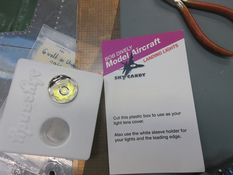
The front metal cover comes off and I cut it down so it's not such a large opening.
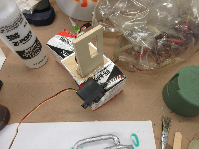
A dubro heavy duty hinge was used to secure light to ply hatch via wood screws and to light via drilling/tapping for machine screws.
Had to make hole in hatch large enough for back of light to clear in the raised position.
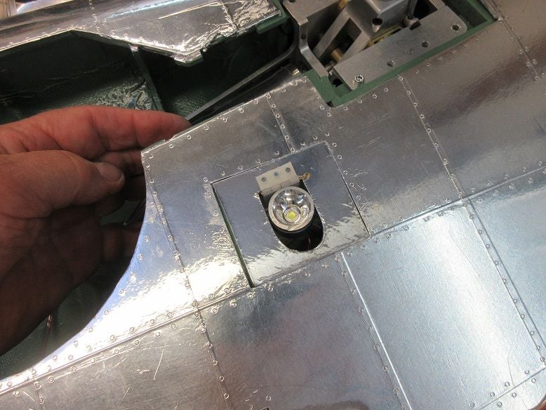
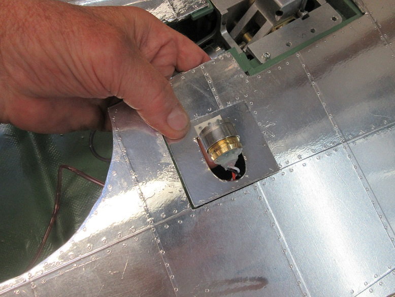
Assembly removable for easy PM.
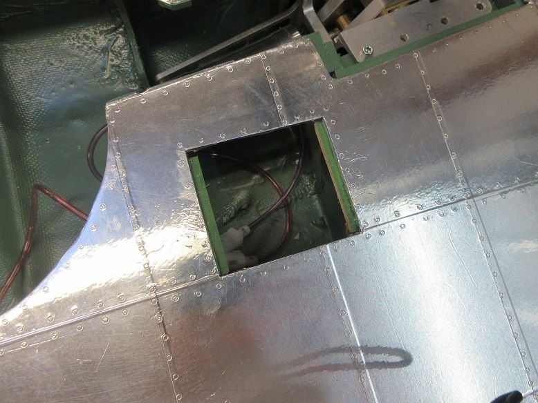
Some lite ply epoxied to hatch cover to hold small servo. Still need to make a lite wire linkage between light and servo arm.
Landing light on left, underside of wing.
Using BVM's high intensity LED landing lights.
Comes with Y wire extension where one part of Y connects to receiver and other to battery source.
Each part of the Y has a sealed circuit board for controlling the light.
With LED's will probably go with receiver power.
Put another Y harness into the gear so one side goes to gear valves and other to landing light.
The front metal cover comes off and I cut it down so it's not such a large opening.
A dubro heavy duty hinge was used to secure light to ply hatch via wood screws and to light via drilling/tapping for machine screws.
Had to make hole in hatch large enough for back of light to clear in the raised position.
Assembly removable for easy PM.
Some lite ply epoxied to hatch cover to hold small servo. Still need to make a lite wire linkage between light and servo arm.
Last edited by samparfitt; 08-09-2019 at 05:24 PM.
 08-10-2019, 02:57 PM
#202
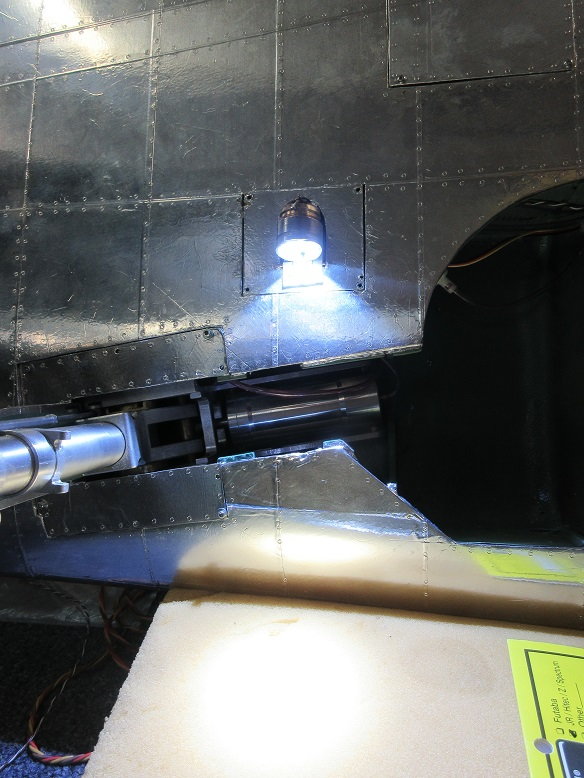
Landing light (cont)
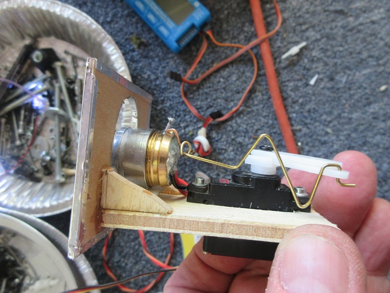
Needed some type of hinge where the linkage connected to the back of the light so a brass wire with a loop was soldered to the light and another loop put on the brass linkage. Some Z bends put in linkage so allow for slop.

Light is very, very bright.
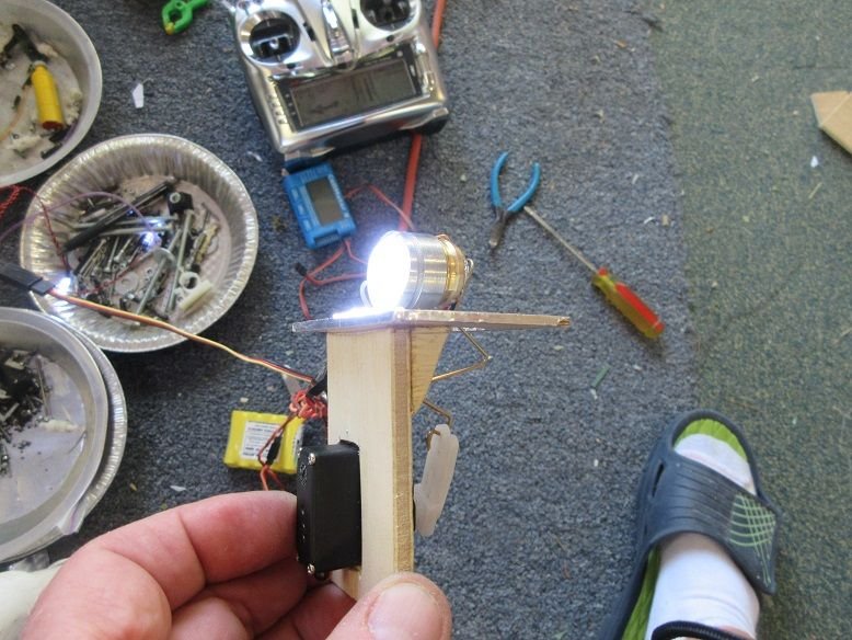
Not pretty but functional.

Needed some type of hinge where the linkage connected to the back of the light so a brass wire with a loop was soldered to the light and another loop put on the brass linkage. Some Z bends put in linkage so allow for slop.
Light is very, very bright.
Not pretty but functional.
08-19-2019, 03:41 PM
#203

My Feedback: (2)
Join Date: Feb 2008
Location: Fullerton, CA
Posts: 101
Likes: 0
Received 0 Likes
on
0 Posts
Sam,
I am trying to decide what to use for my tail wheel. I see you used the Sierra Giant tailwheel. I have both the Sierra Giant tail wheel and a Robart tailwheel. I'm tempted to use the Robart tailwheel as it is much lighter and I don't see any difference as far as looking scale.
Is there a reason why you chose the Sierra Giant tailwheel over the Robart tailwheel?
PS - Your work is unbelievable and I am so glad you have documented your work in such detail. It gives a first timer like me more confidence.
08-19-2019, 04:41 PM
#204
Harry,
I bought the tail wheel since I, also, got his main retracts. Go with what you're comfortable with: The tail wheel is usually hidden in the grass, anyway, and no one sees it. With the doors, it's even less visible.
Thanks for the complements but my work is just average: What's unbelievable is the work done by those attending large warbird scale events.
I like to call my planes 'sport scale'.
I like to document my work 1) good reference for me, later 2) others may have a better solution and 3) it helps my fellow builders.
Ziroli planes are easy to build and easy to fly. Break everything down into modular steps and anyone can build them.
Last edited by samparfitt; 08-20-2019 at 03:51 AM.
08-20-2019, 05:07 PM
#205
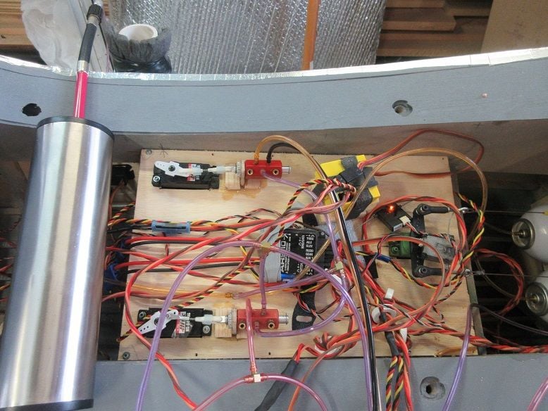
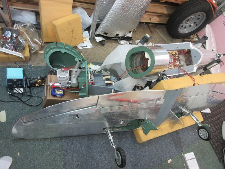
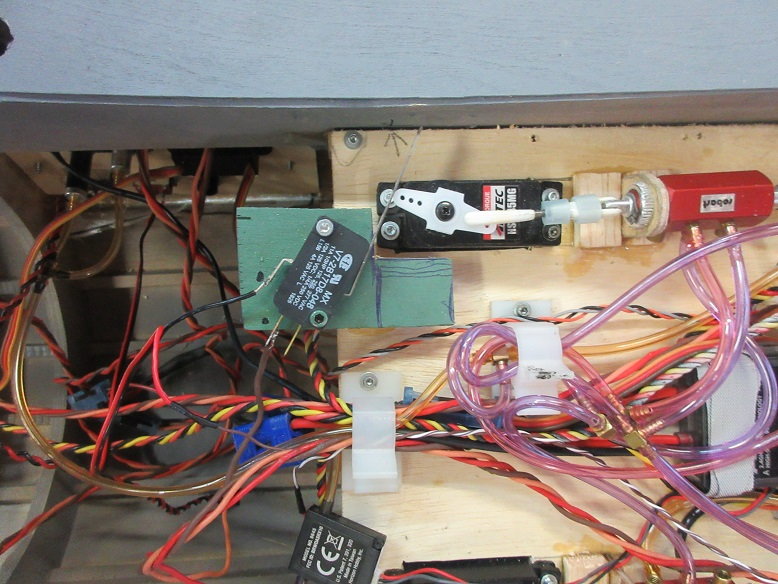
Gear/door activation.
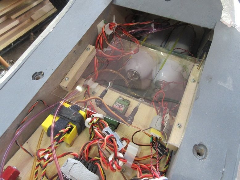
A Jomar electronic gear/door system is being used. One input wire connects to the receiver gear and two servos/valves are connected on the output side.
There are options for P-51/P-47 type doors and speed.
The yellow box is the Jomar device.
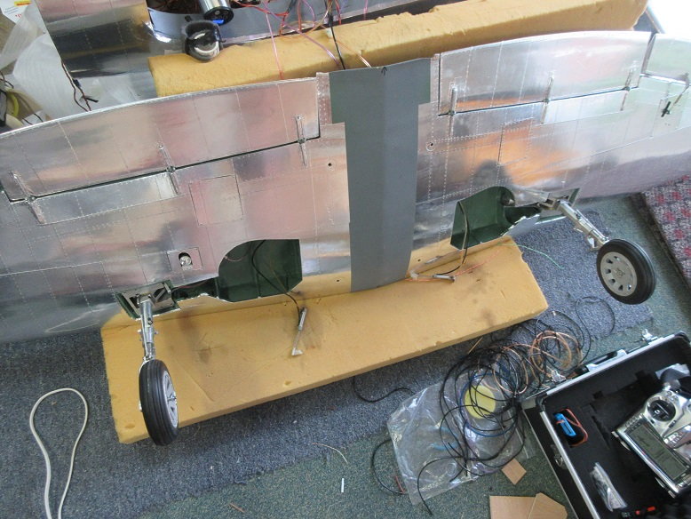
Gear test:
UP
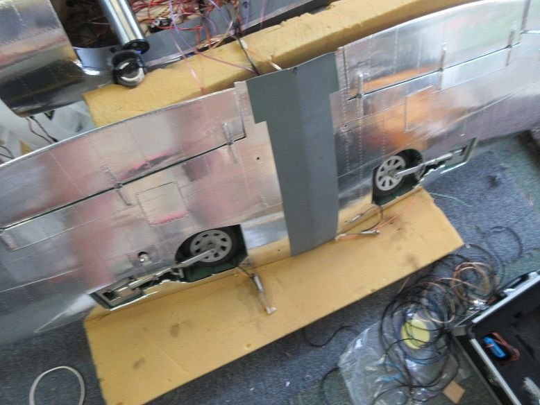
Down.
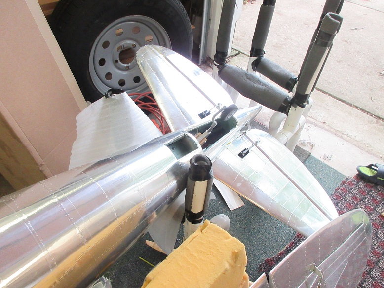
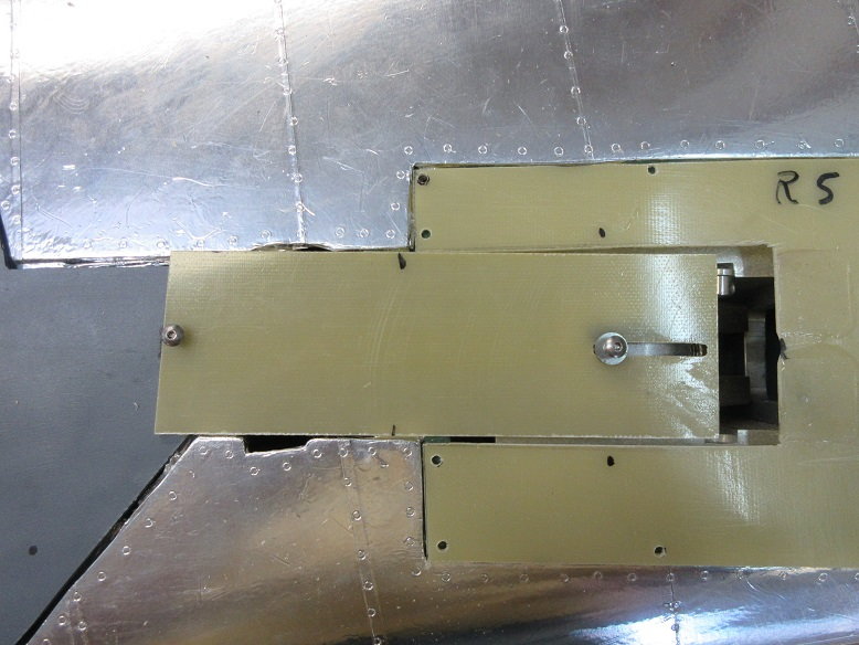
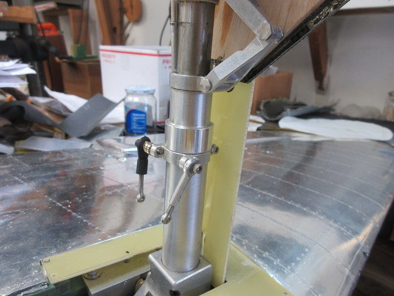
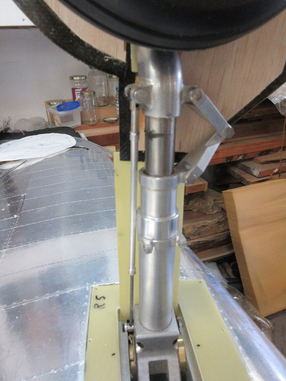
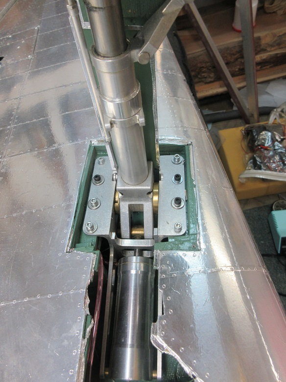
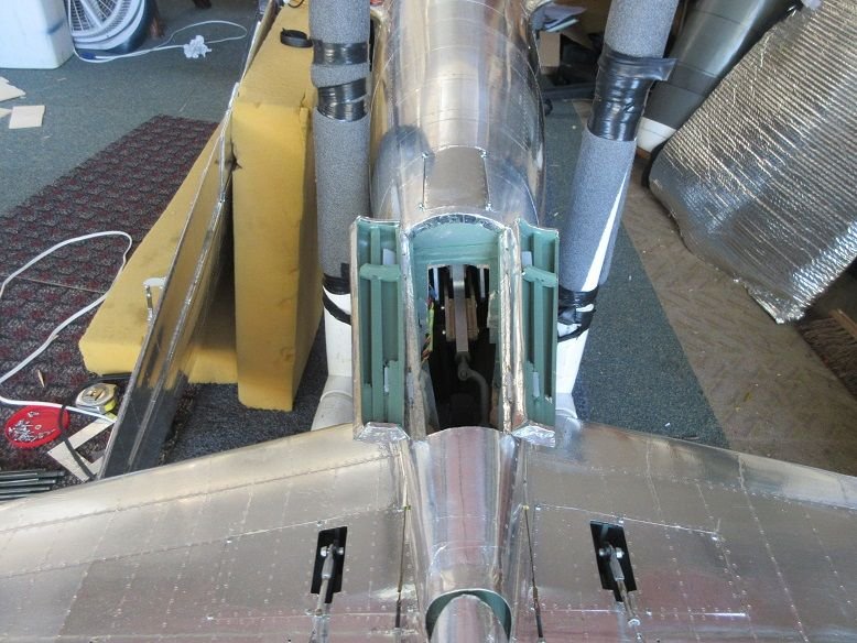
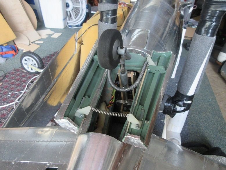
Tail wheel.
Main gear door air cylinders. These are BVM's. They are just right for vertical mounting in the wheel well.
The tail wheel doors will be operated manually via a wire/spring connected the doors and across the tail strut.

A Jomar electronic gear/door system is being used. One input wire connects to the receiver gear and two servos/valves are connected on the output side.
There are options for P-51/P-47 type doors and speed.
The yellow box is the Jomar device.
Gear test:
UP
Down.
Tail wheel.
Main gear door air cylinders. These are BVM's. They are just right for vertical mounting in the wheel well.
The tail wheel doors will be operated manually via a wire/spring connected the doors and across the tail strut.

 08-21-2019, 02:32 AM
#207
Presently, it was a dry tested to make sure all works. I had to move tubing around plus the Jomar has not been fastened down. The wires will be routed/secured and receiver is, also, not secured. The wires/hoses from fuse to wing will be tied together. Probably will use an easy connect for the wires.
08-23-2019, 08:48 AM
#210
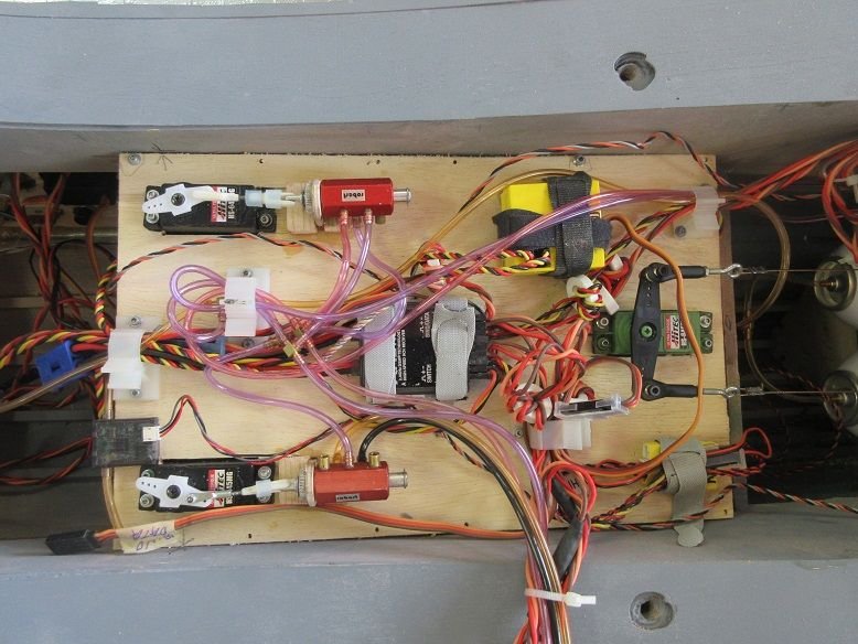
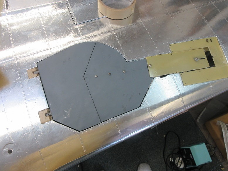
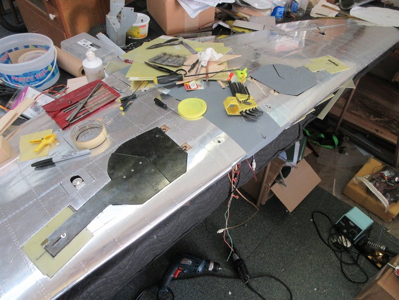
Service tray.
Organized the wires and air lines on the service tray.
Cut off a 1/4" off of each air line since I was moving them around to get the correct sequence for gear/doors and then secured with a 1/16" wide piece of air line for a collar.
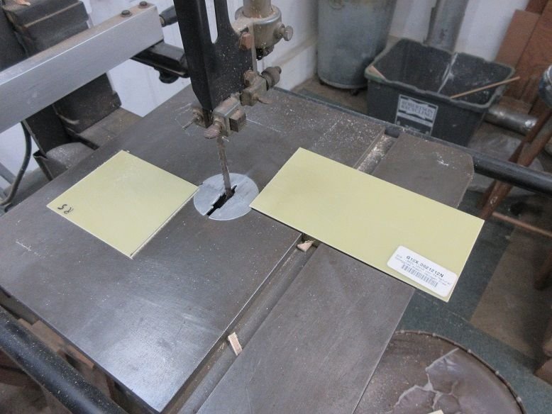
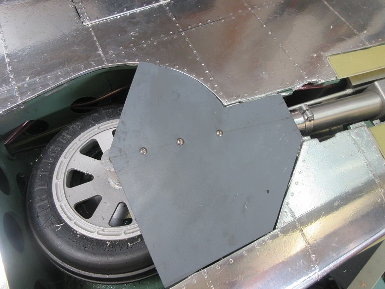
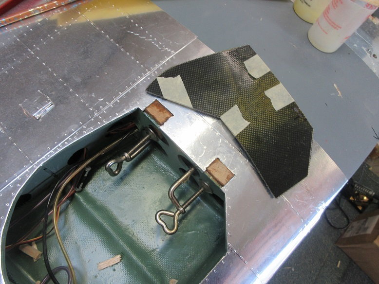
Main gear doors.
G-10 (.062) used for gear frame cover.
I find a band saw works on cutting highly abrasive G-10 and it sands easily with a belt sander.
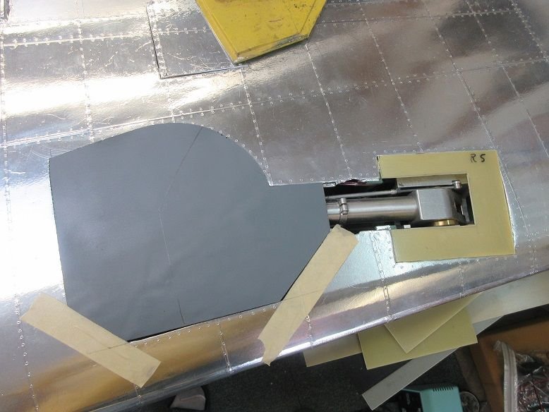
Gear frame cover cut and dry fitted.
Also, had to sand a wedge shaped piece of G-10, and epoxy, to have the gear door align with the wing sheeting.

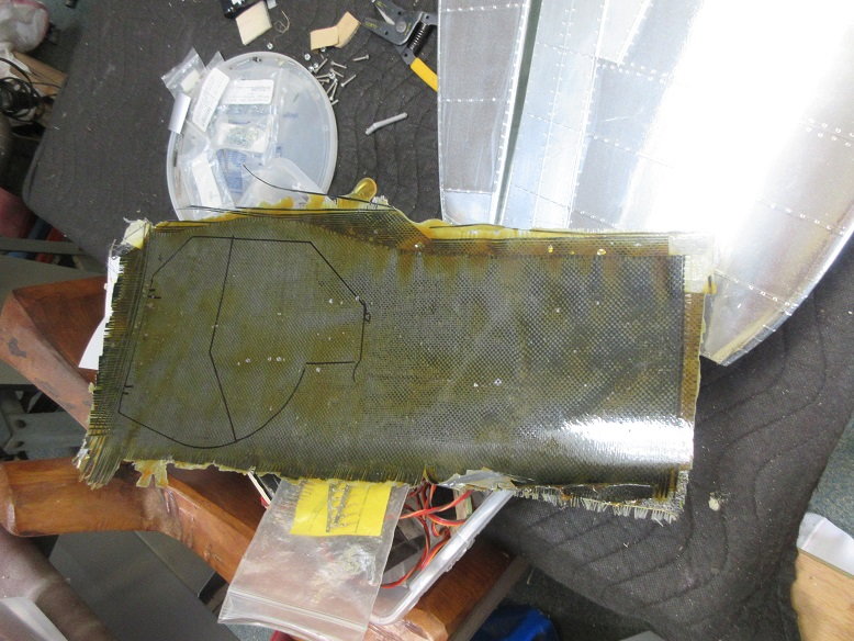
Back before the wheel wells were cut out, some FG covers were made over the existing wing sheeting to get the correct contours.
After cutting and much sanding, the two parts of the gear door fit. Inner door will be hinged and outer door will be screwed to the oleo (after I drill and tap it to the oleo).
Some 1/8" thick balsa sheeting used to build up the inner walls of the doors. Balsa slots cut to allow for robart hinges and contact with the oleos.
The upper door that attaches to the frame cover has no compound curves so it will be cut out of G-10 and hinged to the frame cover.
Hoping to have enough done so I can fly it at Indiana's warbird campaign.

Organized the wires and air lines on the service tray.
Cut off a 1/4" off of each air line since I was moving them around to get the correct sequence for gear/doors and then secured with a 1/16" wide piece of air line for a collar.
Main gear doors.
G-10 (.062) used for gear frame cover.
I find a band saw works on cutting highly abrasive G-10 and it sands easily with a belt sander.
Gear frame cover cut and dry fitted.
Also, had to sand a wedge shaped piece of G-10, and epoxy, to have the gear door align with the wing sheeting.
Back before the wheel wells were cut out, some FG covers were made over the existing wing sheeting to get the correct contours.
After cutting and much sanding, the two parts of the gear door fit. Inner door will be hinged and outer door will be screwed to the oleo (after I drill and tap it to the oleo).
Some 1/8" thick balsa sheeting used to build up the inner walls of the doors. Balsa slots cut to allow for robart hinges and contact with the oleos.
The upper door that attaches to the frame cover has no compound curves so it will be cut out of G-10 and hinged to the frame cover.
Hoping to have enough done so I can fly it at Indiana's warbird campaign.
Last edited by samparfitt; 08-23-2019 at 08:58 AM.
08-23-2019, 02:27 PM
#212
Thanks, Mike,
================
Main gear doors (cont)
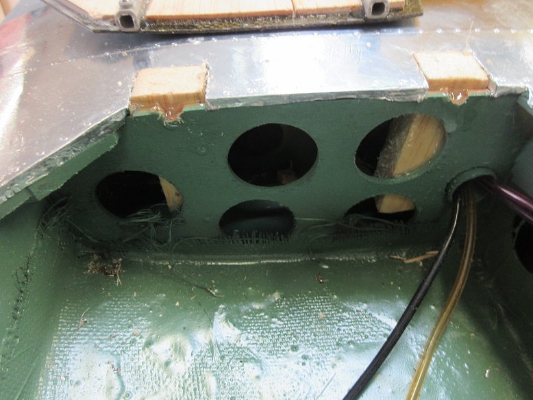
The bottom door to the oleo was drilled/tapped and secured with three 4/40 machine screws.
Robart pocket hinges used on the inner door.
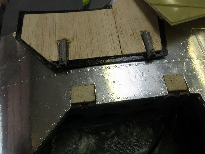
While building the plane, I failed to provide some 'meat' for the door hinges so I had to cut the top wing sheeting and epoxy in some balsa blocks.
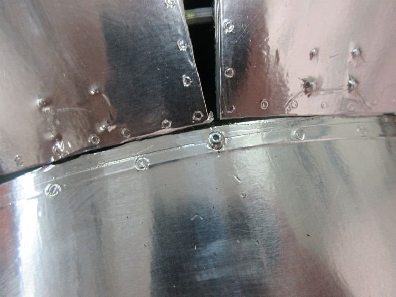
One nice thing about aluminum tape is the surface repair will be very easy
All's working, after much tinkering!
With the shrink bar reducing the gear length by 1 5/8", attaching the upper gear door on a hinge and using a linkage on the oleo was not working as too much movement between the upper door and the oleo.
I attached the upper door to the lower door and made a long slot at the top of the upper door so a screw would guide the door during operation. I drilled/tapped into the oleo for the machine screw. This seems to work well. I can make the upper part of the door longer but will have to make it a little narrower as the door moves towards the gear frame and needs to go between the two sides of the frame (not like anyone is going to see that, anyway!).
I had to put some notches in the wing sheeting to allow for the door linkages but, since the linkages are removed, those notches can be 'filled in'.
The two linkages where the door end would have to travel 1 5/8" from closed to open position.
Shrink bar to compress oleo in the UP position.
================
Main gear doors (cont)
The bottom door to the oleo was drilled/tapped and secured with three 4/40 machine screws.
Robart pocket hinges used on the inner door.
While building the plane, I failed to provide some 'meat' for the door hinges so I had to cut the top wing sheeting and epoxy in some balsa blocks.
One nice thing about aluminum tape is the surface repair will be very easy
All's working, after much tinkering!
With the shrink bar reducing the gear length by 1 5/8", attaching the upper gear door on a hinge and using a linkage on the oleo was not working as too much movement between the upper door and the oleo.
I attached the upper door to the lower door and made a long slot at the top of the upper door so a screw would guide the door during operation. I drilled/tapped into the oleo for the machine screw. This seems to work well. I can make the upper part of the door longer but will have to make it a little narrower as the door moves towards the gear frame and needs to go between the two sides of the frame (not like anyone is going to see that, anyway!).
I had to put some notches in the wing sheeting to allow for the door linkages but, since the linkages are removed, those notches can be 'filled in'.
The two linkages where the door end would have to travel 1 5/8" from closed to open position.
Shrink bar to compress oleo in the UP position.
Last edited by samparfitt; 08-23-2019 at 02:31 PM.
 08-25-2019, 01:30 PM
#214
Thanks, Tom.
=======
Gear doors (cont)
I made imprints of the opposite door on the wrong side so the bend was the wrong way so, while laminating the 1/8" thick balsa on the inside of the doors, I tape/weighted the doors over the curve of the wing while the epoxy dried.
Some more balsa blocks for the inner door hinges.
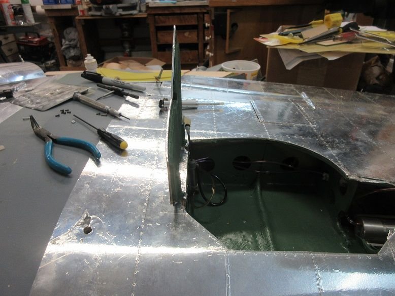
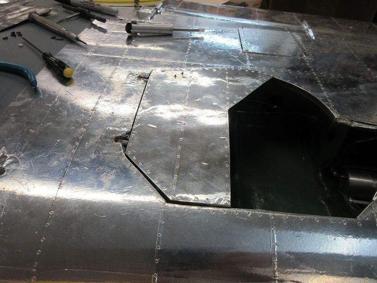
Doors trimmed and fitted.
Inside of doors painted with Rustoleum moss green.

Aluminum tape applied and installed the doors.
Closed
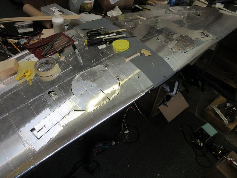
Open.
Next: installing the air cylinders to the inner doors.
=======
Gear doors (cont)
I made imprints of the opposite door on the wrong side so the bend was the wrong way so, while laminating the 1/8" thick balsa on the inside of the doors, I tape/weighted the doors over the curve of the wing while the epoxy dried.
Some more balsa blocks for the inner door hinges.
Doors trimmed and fitted.
Inside of doors painted with Rustoleum moss green.
Aluminum tape applied and installed the doors.
Closed
Open.
Next: installing the air cylinders to the inner doors.
08-25-2019, 04:35 PM
#215
Inner door air cylinders.
That took awhile.
I tried about 5 different methods before getting it to work!
With the wing spar and ribs, when the wheel is in the well, there is limited space to put the air cylinder.
Initially, I used clevises but those were too long and had to cut the end of a ball joint shorter and drill/tap that for air cylinder shaft.
The Robart 1" doesn't move far enough and doesn't sit as low as the BVM air cylinder.
Tried to mount the air cylinder horizontally and using a bell crank but wheel hit it.
The control horn had to be move far enough away from the hinge axis for proper closer.
The air cylinder had to be rotated 180 degrees so the two nipples were facing away from the wall to allow the air cylinder to get close enough to the wall so the door would open all the way.
Air cylinder mounted as low as possible and air nipples away from wall so air cylinder can rotate next to the wall so the door will open, completely.
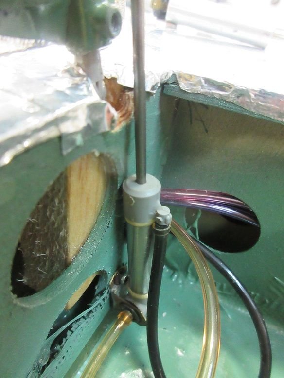
Ball link (white) had to be cut short for full closure of the door.
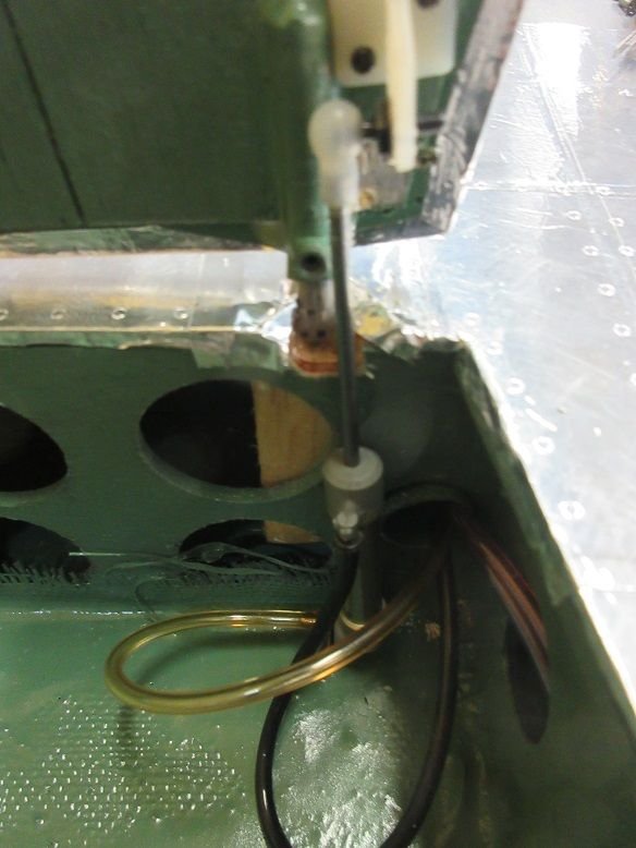
The door just closes all the way, there is no margin for slop/error.
That took awhile.
I tried about 5 different methods before getting it to work!
With the wing spar and ribs, when the wheel is in the well, there is limited space to put the air cylinder.
Initially, I used clevises but those were too long and had to cut the end of a ball joint shorter and drill/tap that for air cylinder shaft.
The Robart 1" doesn't move far enough and doesn't sit as low as the BVM air cylinder.
Tried to mount the air cylinder horizontally and using a bell crank but wheel hit it.
The control horn had to be move far enough away from the hinge axis for proper closer.
The air cylinder had to be rotated 180 degrees so the two nipples were facing away from the wall to allow the air cylinder to get close enough to the wall so the door would open all the way.
Air cylinder mounted as low as possible and air nipples away from wall so air cylinder can rotate next to the wall so the door will open, completely.
Ball link (white) had to be cut short for full closure of the door.
The door just closes all the way, there is no margin for slop/error.
08-26-2019, 01:33 PM
#216
Main gear doors:
Having done the right door, it was quick work getting the left inner door to work.
Re-bound the receiver to set the servos to the desired position.
Put in the remaining bolts into the main gear: with 8 bolts, it should be secure!
Made up extension wires for the nav lights.
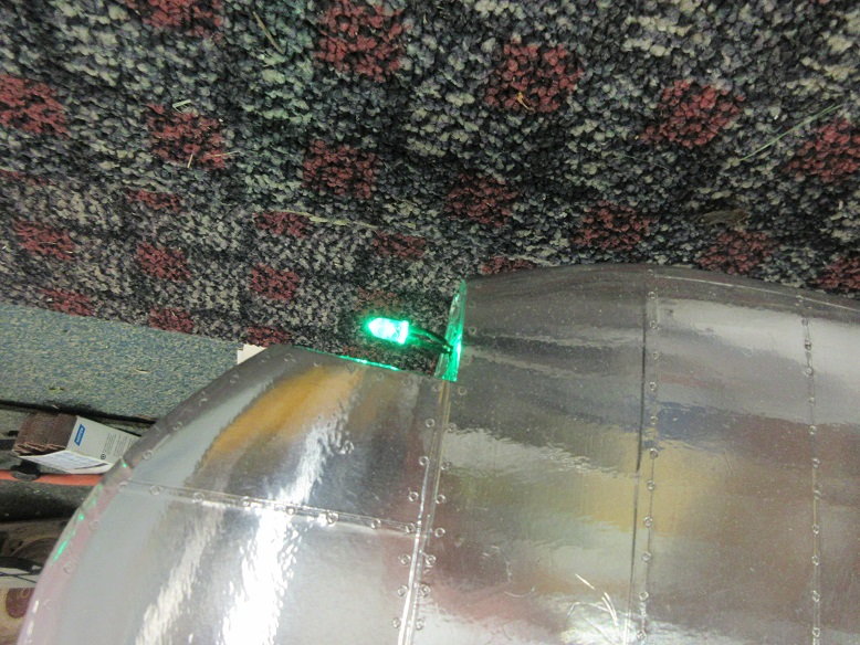
as well as for the landing light.
Still need to install a contact switch in line with the gear servo arm to turn the light off in the UP position.
I forgot to install wires for the rudder nav light. With getting this plane ready by tomorrow for Muncie, presently, no time for that.
Been raining all day today and not sure how much for tomorrow but need to get her assembled and test the engine and set the CG.
Having done the right door, it was quick work getting the left inner door to work.
Re-bound the receiver to set the servos to the desired position.
Put in the remaining bolts into the main gear: with 8 bolts, it should be secure!
Made up extension wires for the nav lights.
as well as for the landing light.
Still need to install a contact switch in line with the gear servo arm to turn the light off in the UP position.
I forgot to install wires for the rudder nav light. With getting this plane ready by tomorrow for Muncie, presently, no time for that.
Been raining all day today and not sure how much for tomorrow but need to get her assembled and test the engine and set the CG.
08-27-2019, 12:35 PM
#217
Stuff:
Installed contact switch next to gear servo to activate the landing gear light when gear is down.
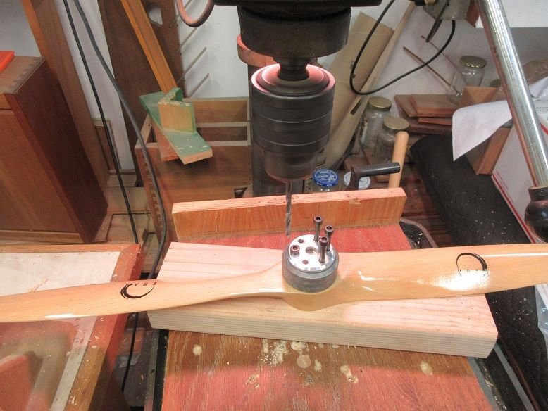
Drilled 6 holes in a 26X12 prop for the DA-85. Also, drilled from the other side to insure perpendicular plus used next size drill bit to enlarge holes a tad for slop. Even with a drill jig and drill press, putting on the prop is always a tight fit.
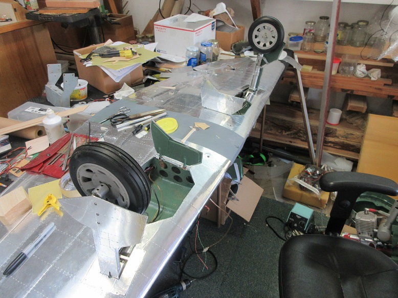
First time on her feet with all equipment.
Got 1670/5840 RPM's. I prefer around 6500 but adjusting the high end didn't help. Screw setting seem correct as great response from throttle movement.
DA manual says 6200 or higher and recommended props: 27X10, 26X12. I'll have to see if I have a Mejzlik prop.
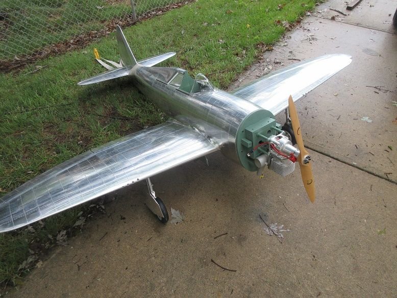


CG at 5.5".
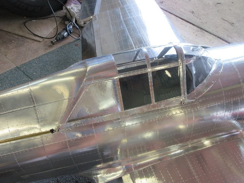
Slid canopy on for now without cockpit detail. Used a servo black rubber bushing in the rail slot to hold canopy closed.
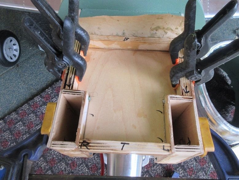
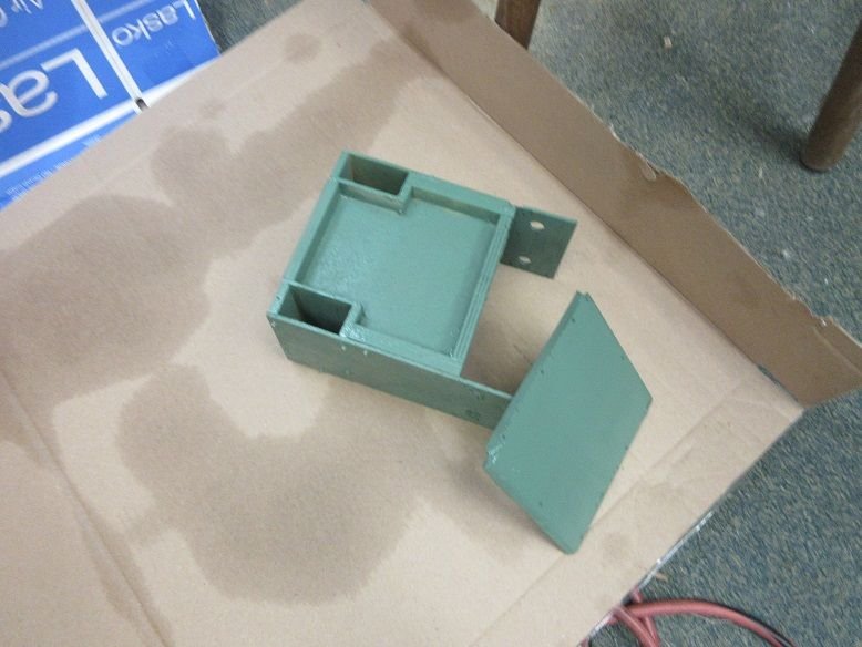
Making lead holder. Two saddle boxes on each side plus a tray on top to fill with lead buckshot. Still need to make a removable top cover.
Used 1/8" thick aircraft ply for the sides, bottom and 1/4" to 3/8" thick ply for some side and places to screw the top. The lead holder straddles the engine box and 12 screws hold the lead holder to the sides of the engine box so it's removable. Took the bulk of the day to make it! Epoxied and screwed together.

The first thing I did after making the initial two sides that straddle the engine box is make sure the cowl fit. Had to trim some on the ply where the cowl flaps servos are located.

Installed contact switch next to gear servo to activate the landing gear light when gear is down.
Drilled 6 holes in a 26X12 prop for the DA-85. Also, drilled from the other side to insure perpendicular plus used next size drill bit to enlarge holes a tad for slop. Even with a drill jig and drill press, putting on the prop is always a tight fit.
First time on her feet with all equipment.
Got 1670/5840 RPM's. I prefer around 6500 but adjusting the high end didn't help. Screw setting seem correct as great response from throttle movement.
DA manual says 6200 or higher and recommended props: 27X10, 26X12. I'll have to see if I have a Mejzlik prop.
CG at 5.5".
Slid canopy on for now without cockpit detail. Used a servo black rubber bushing in the rail slot to hold canopy closed.
Making lead holder. Two saddle boxes on each side plus a tray on top to fill with lead buckshot. Still need to make a removable top cover.
Used 1/8" thick aircraft ply for the sides, bottom and 1/4" to 3/8" thick ply for some side and places to screw the top. The lead holder straddles the engine box and 12 screws hold the lead holder to the sides of the engine box so it's removable. Took the bulk of the day to make it! Epoxied and screwed together.
The first thing I did after making the initial two sides that straddle the engine box is make sure the cowl fit. Had to trim some on the ply where the cowl flaps servos are located.
Last edited by samparfitt; 08-27-2019 at 12:41 PM.
08-27-2019, 12:58 PM
#218

My Feedback: (1)
Join Date: Sep 2004
Location: Charlotte,
NC
Posts: 112
Likes: 0
Received 0 Likes
on
0 Posts
Looks great, Sam. I check for your posts daily. You've been a HUGE help to me while building mine. I've used many of your ideas and methods. I just wish my progress was as fast as yours!
So how much total weight are you going to have to add to the nose? With the nose weight, what is the total weight of the plane?
Thanks,
Glenn
So how much total weight are you going to have to add to the nose? With the nose weight, what is the total weight of the plane?
Thanks,
Glenn
08-27-2019, 06:53 PM
#219
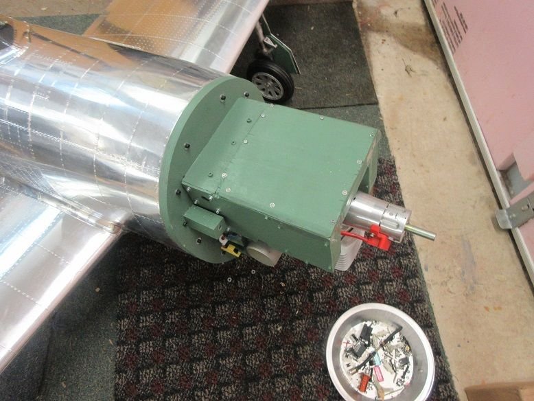
More stuff:
Painted the weight box.
Buckshot added.
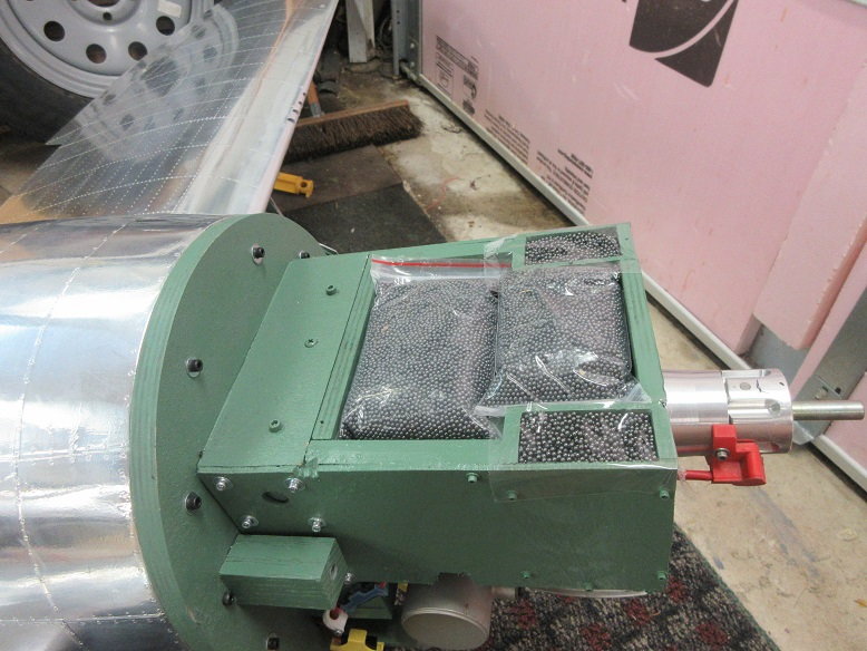
cover screwed down.
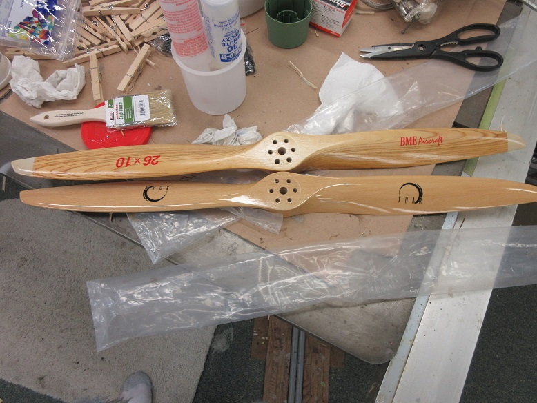
Finally learned how to drill bolt holes in the props. I was using the engine prop plate over the prop jig and the prop plate has a slightly smaller diameter than the prop jig. The jig uses a 13/64" bit which is just a hair larger than the prop plates, but it made a big difference: no binding when putting on the prop. The smaller diameter bit allowed to be off center a hair: the prop jig allows a little slop but guides a correct diameter bit correctly. I was using the prop plate to make sure I didn't drill the wrong holes but, instead, I just mark the holes.

Found a couple 26X10 and they gave me 6300 RPM's so better than the 27X12's/
Cowl attached to fire wall using 4 screws located inside the cowl.
A 4-blade would look much better.
When I get back from Muncie, I'll finish up the cockpit and add decals. Also, tail wheel doors.

Per Darrell, use grease on the axles on large planes. Put a nylon washer between oleo and wheel to take up slop in the side movement. Also, bent the cotter pin and checked all set screws on axle and upper part of oleo.

Belly pan checked for fit.

Almost forgot to add the button head screws to secure cowl to ply insert plus Hysol.
Noticed the oleos weren't working. Had the upper doors too wide and they hit the gear frame. Had to cut about a 1/4" wide by an inch long off the sides.
Painted the weight box.
Buckshot added.
cover screwed down.
Finally learned how to drill bolt holes in the props. I was using the engine prop plate over the prop jig and the prop plate has a slightly smaller diameter than the prop jig. The jig uses a 13/64" bit which is just a hair larger than the prop plates, but it made a big difference: no binding when putting on the prop. The smaller diameter bit allowed to be off center a hair: the prop jig allows a little slop but guides a correct diameter bit correctly. I was using the prop plate to make sure I didn't drill the wrong holes but, instead, I just mark the holes.
Found a couple 26X10 and they gave me 6300 RPM's so better than the 27X12's/
Cowl attached to fire wall using 4 screws located inside the cowl.
A 4-blade would look much better.
When I get back from Muncie, I'll finish up the cockpit and add decals. Also, tail wheel doors.
Per Darrell, use grease on the axles on large planes. Put a nylon washer between oleo and wheel to take up slop in the side movement. Also, bent the cotter pin and checked all set screws on axle and upper part of oleo.
Belly pan checked for fit.
Almost forgot to add the button head screws to secure cowl to ply insert plus Hysol.
Noticed the oleos weren't working. Had the upper doors too wide and they hit the gear frame. Had to cut about a 1/4" wide by an inch long off the sides.
Last edited by samparfitt; 08-27-2019 at 06:56 PM.
08-27-2019, 08:08 PM
#220
Glenn,
Thanks. Glad the thread has helped in your build.
Don't know how much weight I added plus the plane weight is not know: never weigh them (can't remove it anyway so never bother). Ziroli planes fly well whether they weigh 32 pounds or 42 pounds.
Thanks. Glad the thread has helped in your build.
Don't know how much weight I added plus the plane weight is not know: never weigh them (can't remove it anyway so never bother). Ziroli planes fly well whether they weigh 32 pounds or 42 pounds.
Last edited by samparfitt; 08-28-2019 at 03:48 AM.
09-01-2019, 03:13 PM
#222
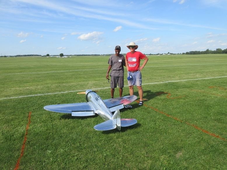
Maiden plus 3.
All went well. Had to put a whole 2 clicks in the elevator for level flight.
Had my buddy, Chris do the honors. There was a lot of turbulence over the tents on landing so I left the 'expert' handle the flying.
The bright landing light looks cool.
Maiden:
I forgot to put the servo arm screw in one aileron so rolls were sluggish!
2nd-3rd flight: all's good.
4th flight: wheel fell off when put in the down position but landed OK (doors got beat up). The Tuesday before I left for Muncie, I specifically checked the two set screws to hold the axle on plus there were two flat spots for the set screws, yet the wheel still came off. Locktite this time!
Now I can do the rest of the 'bells and whistles'.
video of the maiden will be posted after upload.
Last edited by samparfitt; 09-01-2019 at 04:34 PM.
09-03-2019, 03:46 AM
#223
Maiden flight:
There was some sever turbulence coming over the tents and pilots were having trouble landing so I let my buddy, Chris, do the honors. You can hear the wind in the video: pretty strong cross wind.
She was nose heavy so weight was taken out on the 2nd flight. Also, on this flight, I forgot to put the servo arm screw in one aileron and servo arm came off.
Two clicks on elevator was the only adjustment.
Most of the time, Chris only flew her at about 50% throttle.
He did rolls and loops. With only one aileron, the rolls were sluggish.
The landing light is nice and bright on landing. I had to remove the access door since I forgot to put a magnet on it and the prop wash kept opening it.
Left off some 'bells and whistles' so I could have her flying in time for Muncie.
Starts at 33 minutes into the video:
Last edited by samparfitt; 09-03-2019 at 10:12 AM.
09-03-2019, 03:23 PM
#225
Thanks. Andy took it.
=====
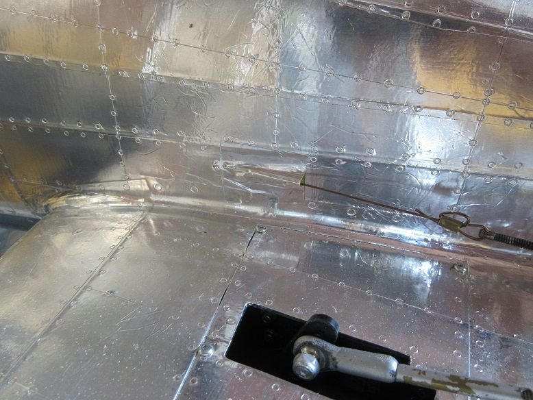
Stuff:
Service tray.
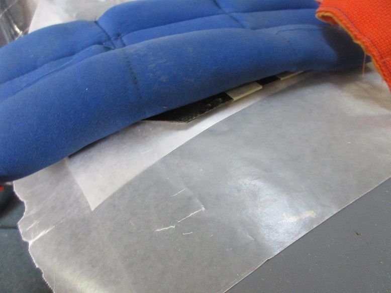
Put some light plastic over the pull/pull cables for the rudder as there is about 2' of wires/air lines between the wing and fuse that lay in that area when I put the wing on the fuse.
Magnets added to the hatch door.

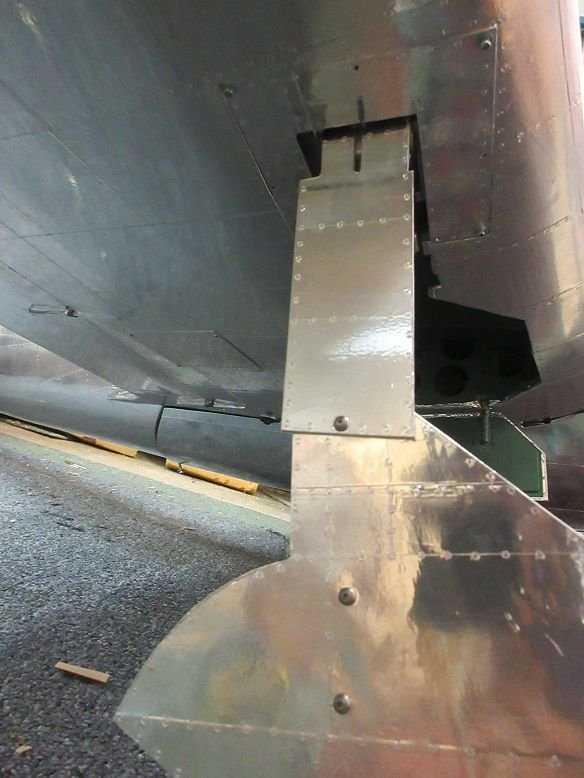
Darrell's tail gear is mounted on a flat ply in front of the gear door.
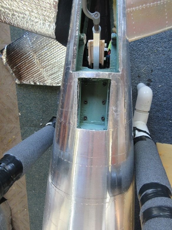
The original sheeted piece was aluminum covered and screwed in place.
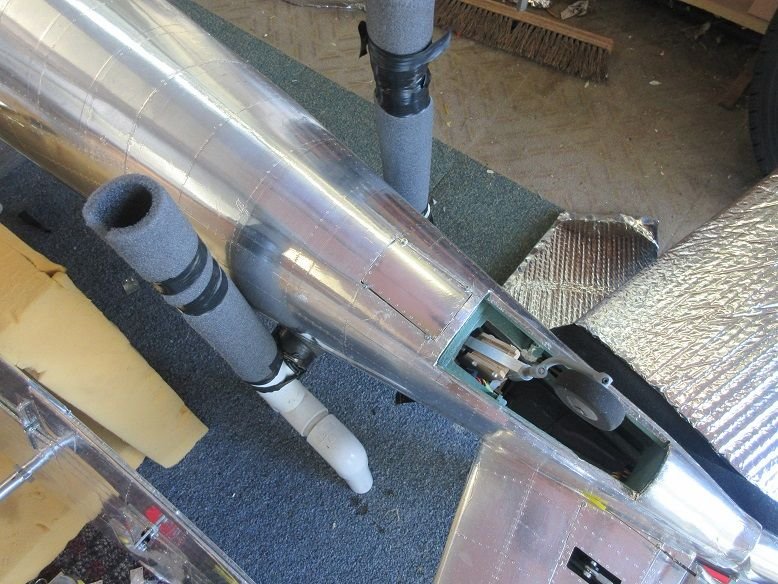
Same with tail gear doors: original pieces used for the doors.
Dry fit with dubro's heavy duty nylon hinges.
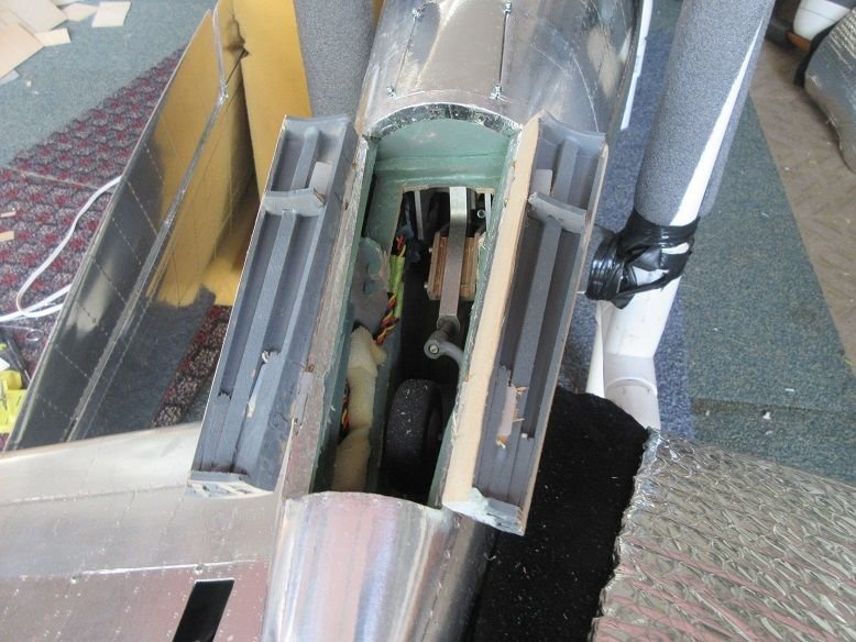
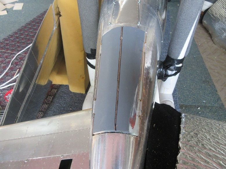
Inner doors painted moss green and aluminum on the outside surface.

Got a bag of springs from the shop and picked two that seemed right for the job. Used dubro small control horns to secure the springs. The longer spring was cut twice, each time about 3/4" off, to get the proper tension to close the doors. The near one 'pops' the doors open and the gear pulls down on the back one to close the doors.
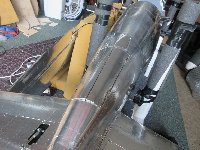
Put a piece of aluminum tape over the sullivan yellow nylon rod used to guide the pull/pull cables.
=====
Stuff:
Service tray.
Put some light plastic over the pull/pull cables for the rudder as there is about 2' of wires/air lines between the wing and fuse that lay in that area when I put the wing on the fuse.
Magnets added to the hatch door.
Darrell's tail gear is mounted on a flat ply in front of the gear door.
The original sheeted piece was aluminum covered and screwed in place.
Same with tail gear doors: original pieces used for the doors.
Dry fit with dubro's heavy duty nylon hinges.
Inner doors painted moss green and aluminum on the outside surface.
Got a bag of springs from the shop and picked two that seemed right for the job. Used dubro small control horns to secure the springs. The longer spring was cut twice, each time about 3/4" off, to get the proper tension to close the doors. The near one 'pops' the doors open and the gear pulls down on the back one to close the doors.
Put a piece of aluminum tape over the sullivan yellow nylon rod used to guide the pull/pull cables.
Last edited by samparfitt; 09-03-2019 at 03:29 PM.