Byron F15c Project


 04-13-2020, 06:59 PM
#183
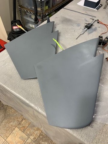
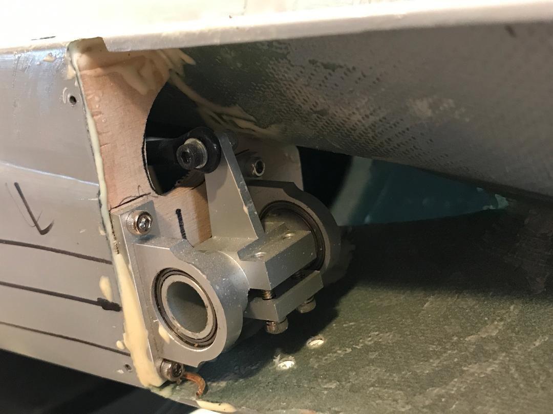
I finished reinforcing the elevators with a heavy rib, covered over with carbon fiber. Also installed a tool steel hardened pivot rod.
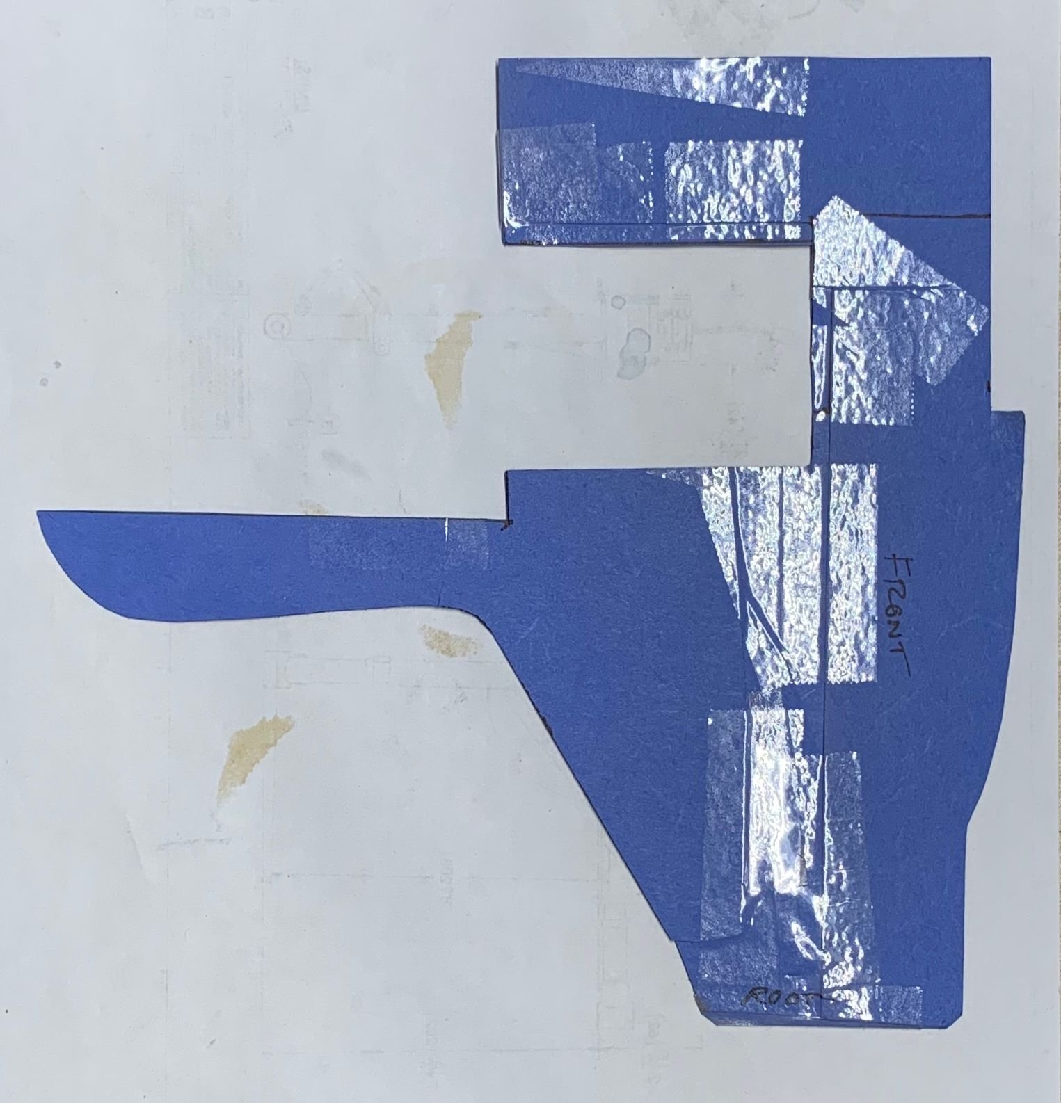
Used construction paper to piece together the profile for the landing gear support formers.
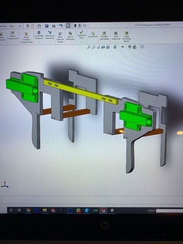
Took a pic of the paper former, imported it into Solidworks, scaled it, and designed the actual cad gear support parts.
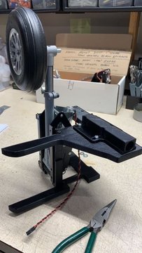
3D printed the formers to do a final fit check before actually machining the formers.
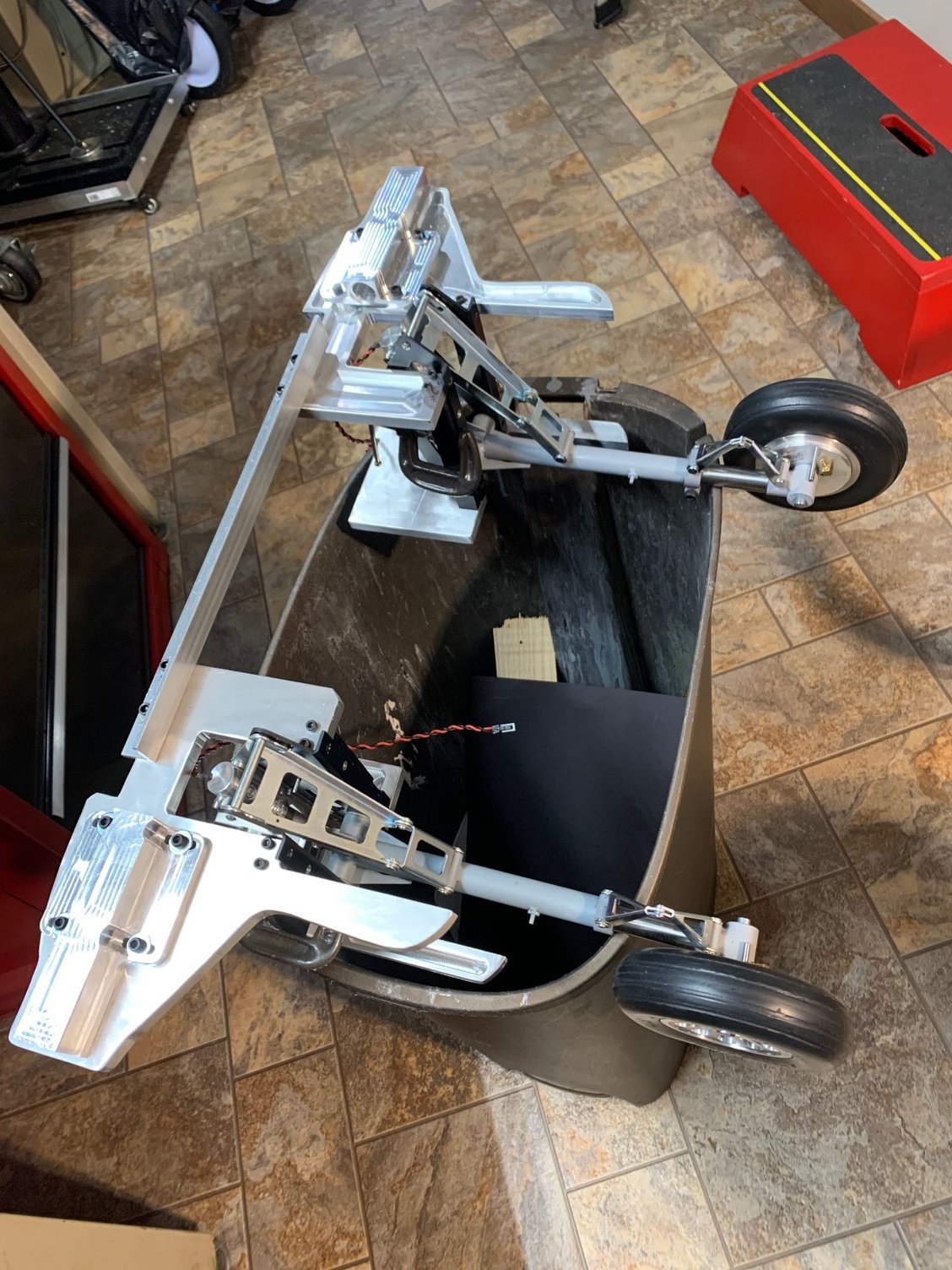
Everything in place, gears work, fit is good with a few design changes.
View from underneath of the left main gear.
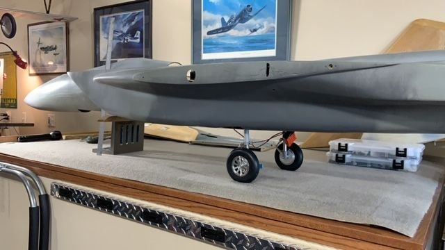
Put the plane on it's back legs and use the stance to design the nose gear supports. I want a tiny negative AOA as it sits on the ground. I will probably have to cut down the strut a little.
11-14-2020, 07:15 AM
#185
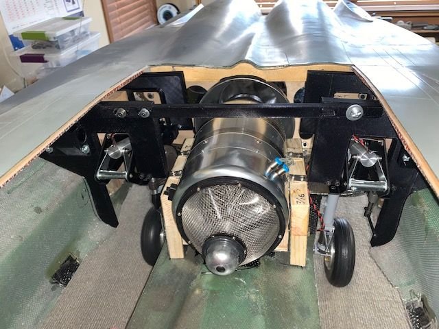
It's been a while since I worked on the F15. I was completing a TopRC Hawker Hunter. I love the look of those early jets. Anyway, I finally got the aluminum formers (of my own design) back from the CNC shop and they are beautiful and fit great. I may add some lightning holes in them, and some glue grooves around the outside edges. I'll have to think if that is needed. Anyway, this structure, which includes new 5/8 dia second-spar tubes, now forms a complete load bearing backbone for the whole jet. I'll be committing to these by gluing them in soon. No going back after that.
Last edited by Pull Up Now!; 11-14-2020 at 08:22 AM.
The following users liked this post:
jescardin (11-14-2020)
11-14-2020, 07:21 AM
#186
Wow, that really look good and strong, you are like me, I stop working on my F-16 and started working on a new DV8R and a used DV8R, the used one is up and flying, new one just need a turbine, good to see you back on the F-15, I will be watching for more build.
11-14-2020, 08:10 AM
#187
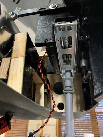
Just for the record, before anyone notices, the retracts are each on the wrong side. The wheels go towards the outside! UPDATE: I fixed it. There are two more tasks before actually gluing these formers into the fuse. First, I need to make the actual flight gear mounting beams. The ones in the picture are still the PLA 3D printed ones. The 5/8" square stock was ordered, and should arrive today. The second task is to machine a tubular spar that will span all the way from the left set of formers to the right set. This will help align the left and right halves while the glue is drying. Later, I'll cut this one long spar in half and they will become the flight spars.
Last edited by Pull Up Now!; 11-14-2020 at 08:28 AM.
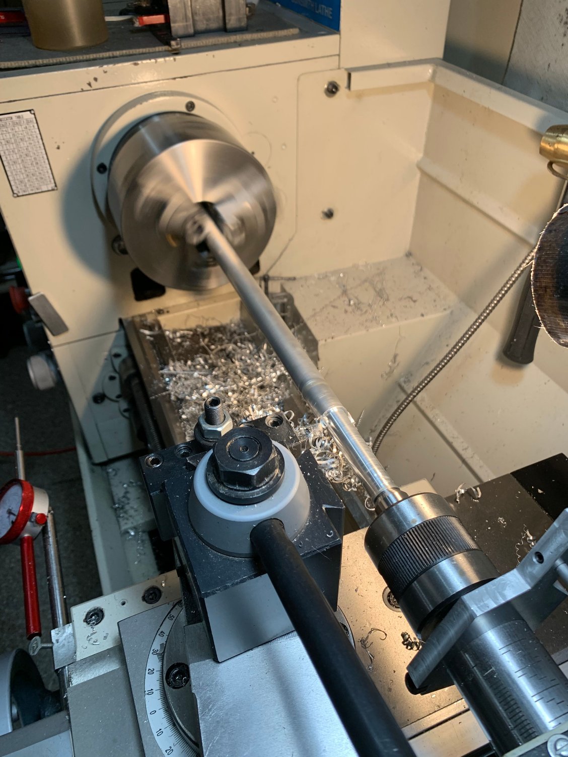
 And with the �double length� alignment spar in place. The length is calculated to be exactly the right length for each side when cut in half.
The following users liked this post:
paulhat (11-15-2020)
11-18-2020, 08:00 PM
#190
The entire gear assembly is now permanently installed in the Byron F15C fuselage. This was a big, long term project, but now it's on to the next task. Fuel tanks. I'd like them as far aft as possible, which will mean a complex custom shape. Probably some CAD work and foam cutting involved. Here's a video of the main gears installed, and working.
12-01-2020, 06:09 PM
#191
I'm pretty much done with the Byron F15C gear installation now. That was a months-long journey. Thanks to Zach Geragi for the excellent CNC machining of my Solidworks design. We have collaborated on a number of projects, including Bob Moore's giant Cessna Citation landing gear, and the Minnesota Giant B1 Lancer model. That last one is huge, it has an 18ft wingspan. We also developed a retrofit servo-operated nose gear steering kit that replaces the troublesome hydraulic steering in the Fly Eagle Jet and Skymaster F16's.
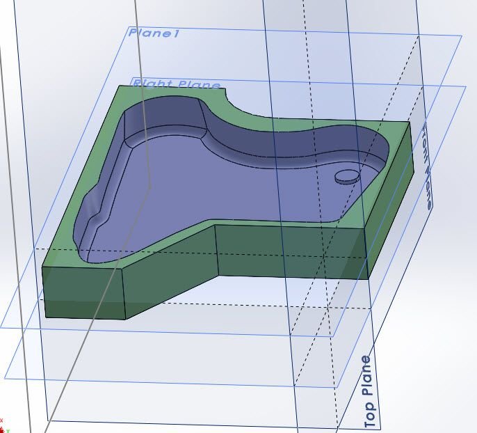
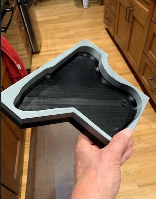
Now, I'm working on some custom fuel tanks. It's a challenge to take advantage of the irregular shaped voids close to the jet's CG in a gas tank design. I designed the tanks, and 3D printed them to make sure they fit. You can see them in the pictures. I actually managed to fill up the wing fillet cavities with "tank". Now that the tanks have been fine tuned a couple times, I'm experimenting with making one-time molds off the 3D printer. The tanks are mirror image models of each other. The first design was great, but the first installed tank blocked the second tank from fitting in, so that was the first big design change. That change made the volume too small, so I had to expand the tanks in other areas. Then the retracted mains interfered, so on to the third iteration, which worked. Now I'm printing the first of the mold pieces. The printed mold are one-time use, and I can break them apart to remove the tank pieces.
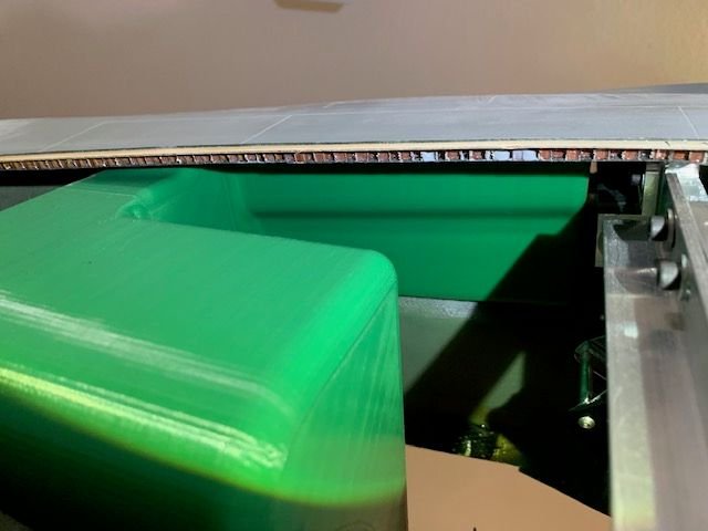

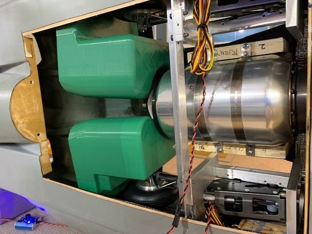
Now, I'm working on some custom fuel tanks. It's a challenge to take advantage of the irregular shaped voids close to the jet's CG in a gas tank design. I designed the tanks, and 3D printed them to make sure they fit. You can see them in the pictures. I actually managed to fill up the wing fillet cavities with "tank". Now that the tanks have been fine tuned a couple times, I'm experimenting with making one-time molds off the 3D printer. The tanks are mirror image models of each other. The first design was great, but the first installed tank blocked the second tank from fitting in, so that was the first big design change. That change made the volume too small, so I had to expand the tanks in other areas. Then the retracted mains interfered, so on to the third iteration, which worked. Now I'm printing the first of the mold pieces. The printed mold are one-time use, and I can break them apart to remove the tank pieces.
Last edited by Pull Up Now!; 12-01-2020 at 06:12 PM. Reason: add picture
12-01-2020, 10:22 PM
#193
Each tank is 220 ounces totalling 440 ounces, which gives about a 9 minute flight at full throttle. But of course I don't fly at full throttle during a flight so I'll land with about 20% left over, maybe enough for one go-around. The Y-pipe came out of a FeiBao F15E and it fit very well. Of course I had to completely redo the original formers to accept the Y-pipe. I really looked over the split carefully on my pipe. There is a stainless steel double piece over that area, but no holes. Have those holes been a problem?
12-01-2020, 11:27 PM
#194

Hi Pull up now
I also made a tailored fuel tank for my Yellow F-16. I 3d printed negative moulds. 2 halves, one with a seam to connect easily.
My surface treatment was like this:
Sand 240 paper
Spray filler, do not spare, make 3 thick layers, then let it dry for 48 hours.
Then wet sand 600 paper, let it dry again. Then I waxed with Partall hi temp wax, 2 times.
Ready to laminate.
12-02-2020, 05:00 AM
#195
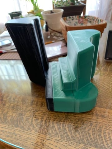
Cetigershark, that's good news you were able to make a printed negative mold. My tank is so odd-shaped that there is no clear parting line and no draft to pop the tank out of the molds. My plan was to destroy the molds to leave the parts, and glue the halves together and wrap the seams later. How many glass layers, and what ounce glass? I was thinking 3 layers of 3 ounce glass, but I've never done this so what's your advise? Here's a pic of the first mold piece. It barely fit on my printer table.
12-02-2020, 05:47 AM
#196
Cetigershark, that's good news you were able to make a printed negative mold. My tank is so odd-shaped that there is no clear parting line and no draft to pop the tank out of the molds. My plan was to destroy the molds to leave the parts, and glue the halves together and wrap the seams later. How many glass layers, and what ounce glass? I was thinking 3 layers of 3 ounce glass, but I've never done this so what's your advise? Here's a pic of the first mold piece. It barely fit on my printer table.
Make sure:
Resin is kerosene proof
corners/edges are a bit reinforced
your last coat to the mould withstands wax/parting agents... I have used 1K filler, and it was not dissolved by the wax. Actually surprising, but I am glad it worked out like that.
12-30-2020, 04:27 PM
#198
I have been following this thread with much interest. I have a Byron F-15 new in box that I purchased about 20 years ago. I have always wanted to install twin 80's in it whenever I got around to building it. Keep the posts coming!!!
The following users liked this post:
mikes68charger (12-31-2020)
02-06-2021, 05:57 PM
#199
This is the stock Byron elevator support, I made a 1/8 former, I did drill 2 big lightning holes, this peace of ply boxes off the one side of wood for inside attachment, this also has glue to all there sides of fuse in this area providing a lot of strength.
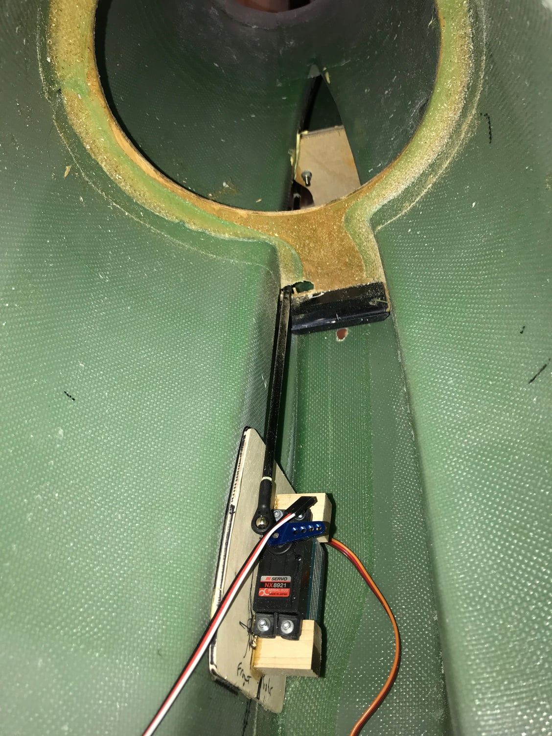
I know some worry about such small elevator tubes, but as these tubes are nothing more than a pivot vs most others where this tube is a pivot and provides rotation forces. Using the stock Byron elevator servo arm for movement gives it 2 points of support,
I do got a sold peace of carbonfiber on order to fit in current elevator rod, I did this on my Byron F16 I converted with JetCat P120SX and never had issues
The following users liked this post:
frankle951 (02-06-2021)
02-09-2021, 11:44 AM
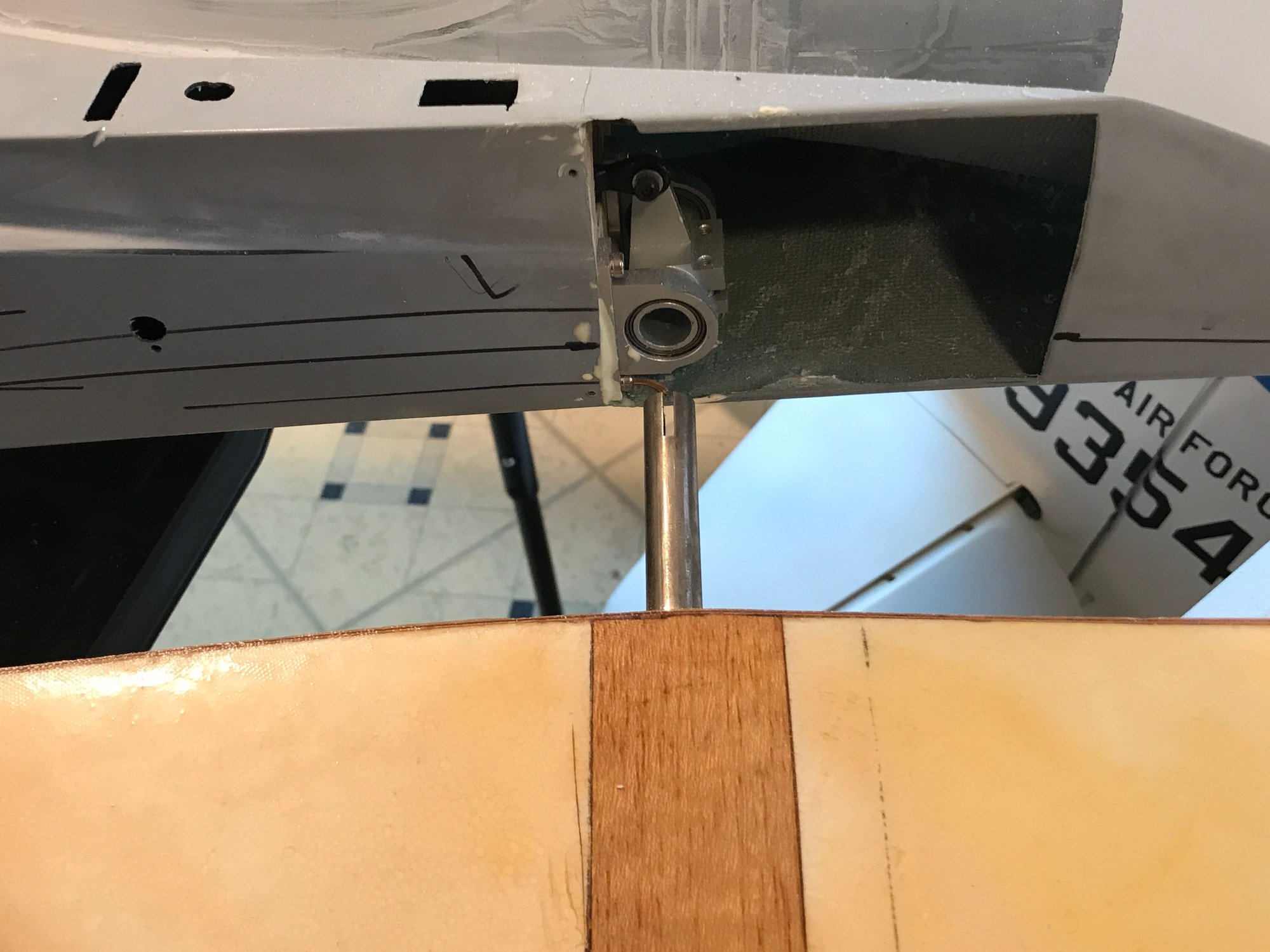
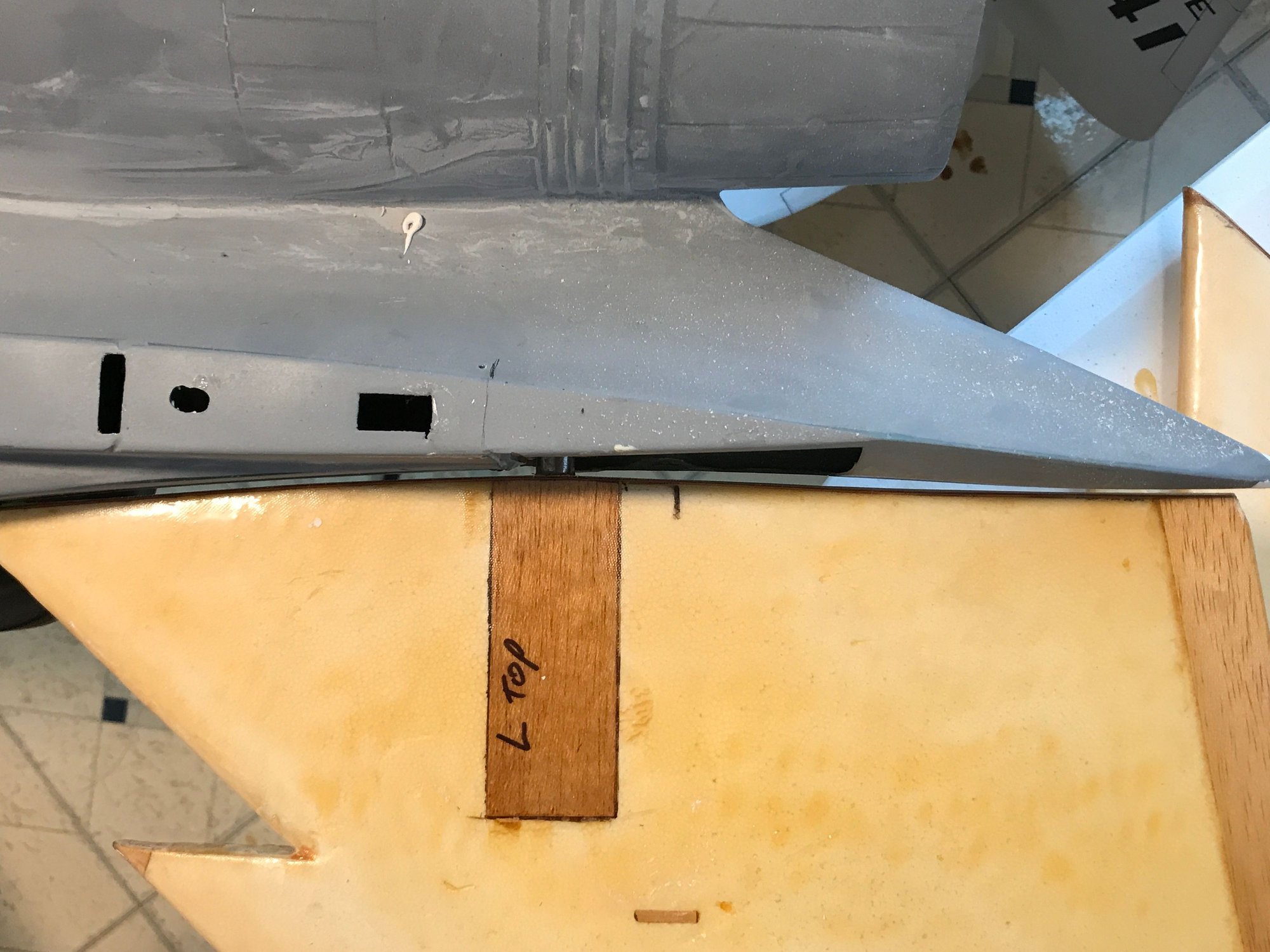
#200

Hello, A friend of mine told me about this thread and I thought I would share the build Im doing on my byron F15. I'll be installing 2 turbines, haven't decided yet on the size. There will be no hatch on the top only two small ones on the bottom to access the Turbines. For the horizontal stab I ordered the mechanism from fabeo that they use on their F15. The stab now plugs in and is bolted down. The pivot point is much different than what byron had.