


Byron F15c Project


 12-02-2019, 04:07 PM
#129

My Feedback: (34)
Well took 2 days But had to completely change the top hatch operation. The skin by it self is like paper.
So I needed to add support from the 2 formers, so I used 2 1/4in hard wood to attach both formers and help build the 1/4in deep inset for the hatch to recess to This let's me build 1/4in (3/16) ply formers. Added some carbonfiber as this section is to close to pipe for a former
Also add 3 front in incerts, rods.to secure the front part. This makes the hatch stronger and the fuse is now stronger
I use servo eyes for all pins that go into wood to prevent the wood hole from getting bigger
Last edited by mikes68charger; 12-02-2019 at 04:16 PM.
 12-02-2019, 06:22 PM
#131


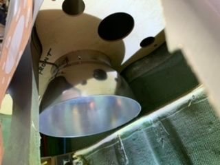
Mike, you're a lot farther along than I am. Shown here is my rear former for the bifurcated pipe. Apparently my pipe is a lot longer than yours is. (I hate the way that sounds). My engine will sit almost between the main gears. There are advantages and disadvantages. The upside is my thrust tube bellmouth has plenty of vertical clearance, so no flat spot needed. The downside is fuel tank location. I also have a 2nd former with one hole that supports the tube forward of the split. Are you putting any heat reflecting material inside?
12-03-2019, 07:42 AM
#132
My Feedback: (34)
Your right, If it was up to me, I would of put the motor farther forward, but someone else already cut the back hatch and got the pipe, so I worked with what I had.
I will add heat alum tape, with some of the BVM white heat paint on the top hatch over the heat tape, there is a small former in the center of the Y pipe, I will screw a thin sheet of alum on it incase the Y pipe burns a hole in the middle, along with a coating of the BVM heat paint, My fear with Y pipes are potential failure in flight, but if it happens you will hear it but you will only have a few sec to turn off motor before major issues. The BVM heat paint will give a few sec of protection, as for the rest of the fuse, is so far away from the pipe I don't see there being any issues, Pulse the way I have my turbine mount, there is light ply under the motor in the hot spot under intake bell.
I added that pipe support former like yours on the inside of the elevator securement attachment point, this way it will be easy to remove the elevators for transport from rear of jet, as for the servo side, there is a sweet, ball link attachment with spring, so you can disconnect with one hand, I added carbon fiber inside the elevator alum rod to provide strength.
Last night I added a 2nd spar to take a lot of load off the factory spar, Ill post pictures tonight, I took a 1/2in peace of carbon fiber tube about 10in long, cut teeth in one side, attaché to drill, to drill inside wing, This will take a 10mm alummum rod I have, I built a ply inside mount with the stock rudder servo wood, this wing tube will be able pulled out for transport.
I'm working on the rudders last night also, I got the servo mounts in nicely, but trying to decide if I will permit attach the rudders, or keep them removable.
This project has been a lot of fun so far, I feel like I'm using a lot of skills that you don't get when just assembling an ARF, but I will say a lot of how I'm building things is based on Skymaster or AIrworld jets I have built in the past.
Fuel is a odd one, I have made my own fuel tanks in the past (for an Aviation Design Diamond Large) But as I have so much space, I just used 2 dubro 80oz fuel tanks in line, Ill post pictures later. I had 2 (64) oz composite fuel tanks with a 60oz middle single tank, but its way easier to have 2 fuel tanks vs 3.
12-03-2019, 08:33 AM
#133
Mike, what is "heat alum tape"? Are you talking about standard HVAC alum ducting tape? Or is this a special product that you're using? Also, you mentioned you're beefing up your elevator pivot spars with carbon on the inside. That's a good thing, but you should consider going beyond that. I used a stud sensor to locate the end of the alum tube in the elevator. I then cut out a little square and discovered there are no ribs inside surrounding that spar. I've seen elevator spars blow right thru the skin in flight because there are no ribs, or the rib is too thin where the spar goes thru. I will be digging two channels and adding ribs to prevent this. You may want to consider doing so too.
12-03-2019, 11:41 AM
#134
My Feedback: (34)
Mike, what is "heat alum tape"? Are you talking about standard HVAC alum ducting tape? Or is this a special product that you're using? Also, you mentioned you're beefing up your elevator pivot spars with carbon on the inside. That's a good thing, but you should consider going beyond that. I used a stud sensor to locate the end of the alum tube in the elevator. I then cut out a little square and discovered there are no ribs inside surrounding that spar. I've seen elevator spars blow right thru the skin in flight because there are no ribs, or the rib is too thin where the spar goes thru. I will be digging two channels and adding ribs to prevent this. You may want to consider doing so too.
As for the wing strength, as I now have 2 spars, my fear is not as high as before. I will cut the balsa off the foam over the top of the factory alum spar about 4in wide and take it to close to the wing edge. I will replace this balsa with fiberglass plate (like flight skin just thicker) which is almost as strong as carbonfiber, but this stuff being fiberglass with seal better when I cover the whole wing with fiberglass cloth.
After talking to my buddy, I think for the motor hatch, I will do the alum heat sheld, buy getting a very thin sheet of alum, drill holes, screw hard wood blocks on back side about 4mm thick, then epoxy these to the top of the hatch, this will help dispute the heat better.
12-03-2019, 02:55 PM
#136
My Feedback: (34)
Yes that's the tape I use, I put a thin bead of 100% silicone throw the center of the strip to help hold on when upside down.
Also in your other project that the pipe is much close to fuse, I have rap the pipe with Header rap from Autozone, its design to rap car and motorcycle headers, it helps keep heat in pipe.
I believe BVM and seen others use the fiberglass mat like the stuffing in your oven as a heat blanket
Also in your other project that the pipe is much close to fuse, I have rap the pipe with Header rap from Autozone, its design to rap car and motorcycle headers, it helps keep heat in pipe.
I believe BVM and seen others use the fiberglass mat like the stuffing in your oven as a heat blanket

 12-03-2019, 06:39 PM
#139
My Feedback: (34)
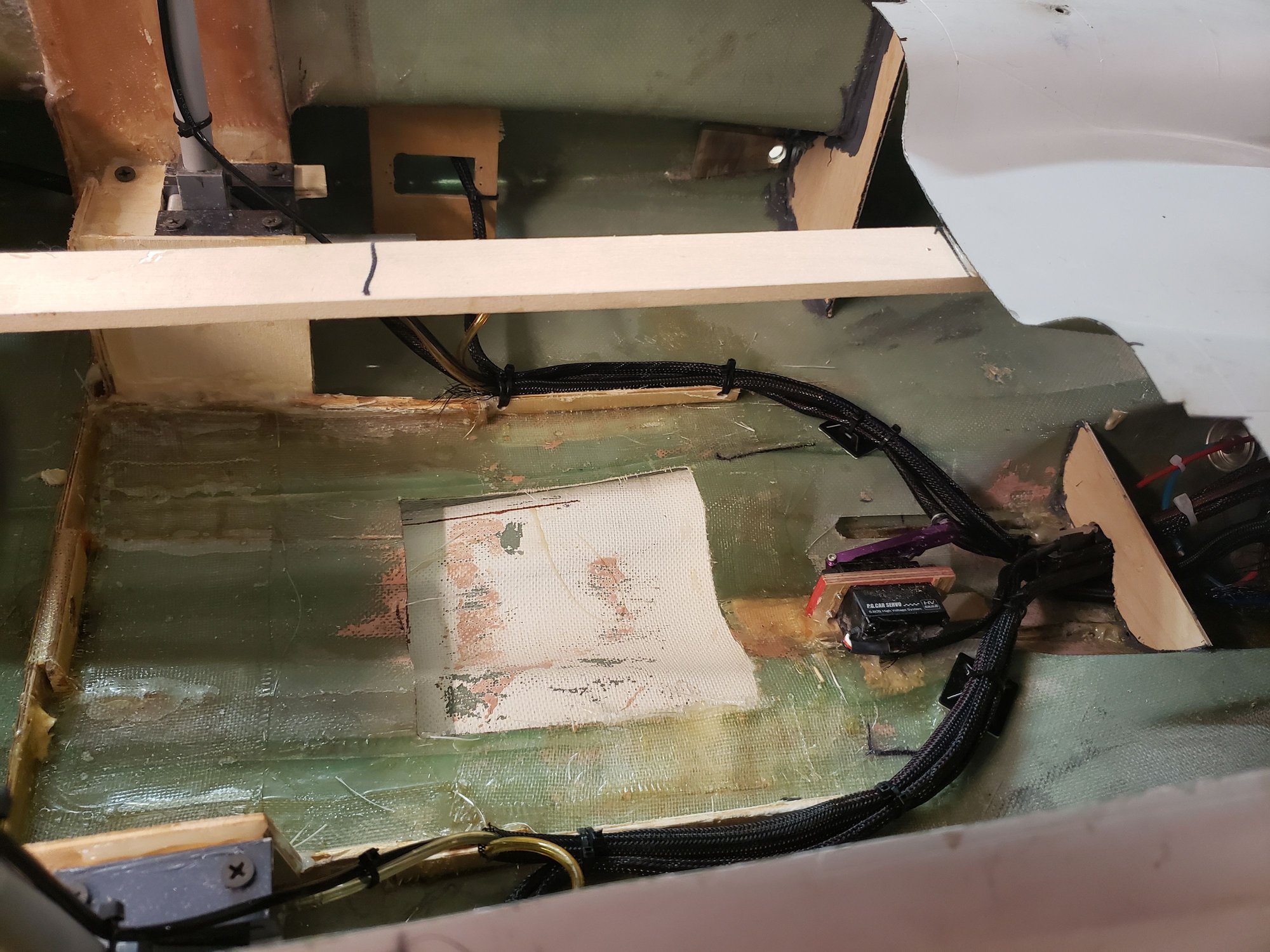
So wireing harnesses and air harnesses are done, all net, as and covered in sheath to protect wires and hoses
Aluminum heat shield on the only part that will be close to the pipe, and radiates up. Made out of thin aluminum with 4mm wood spacers glued to top hatch
Fuel tanks were done a few days back Used 1/4in ply strips to build a frame around the new Dubro 80oz fuel tanks, I used plastic epoxy to help secure it to frame along with silicone, once I'm done on inside it will get set in with the 3 mounting points being glued for easy removal buy 3 screws
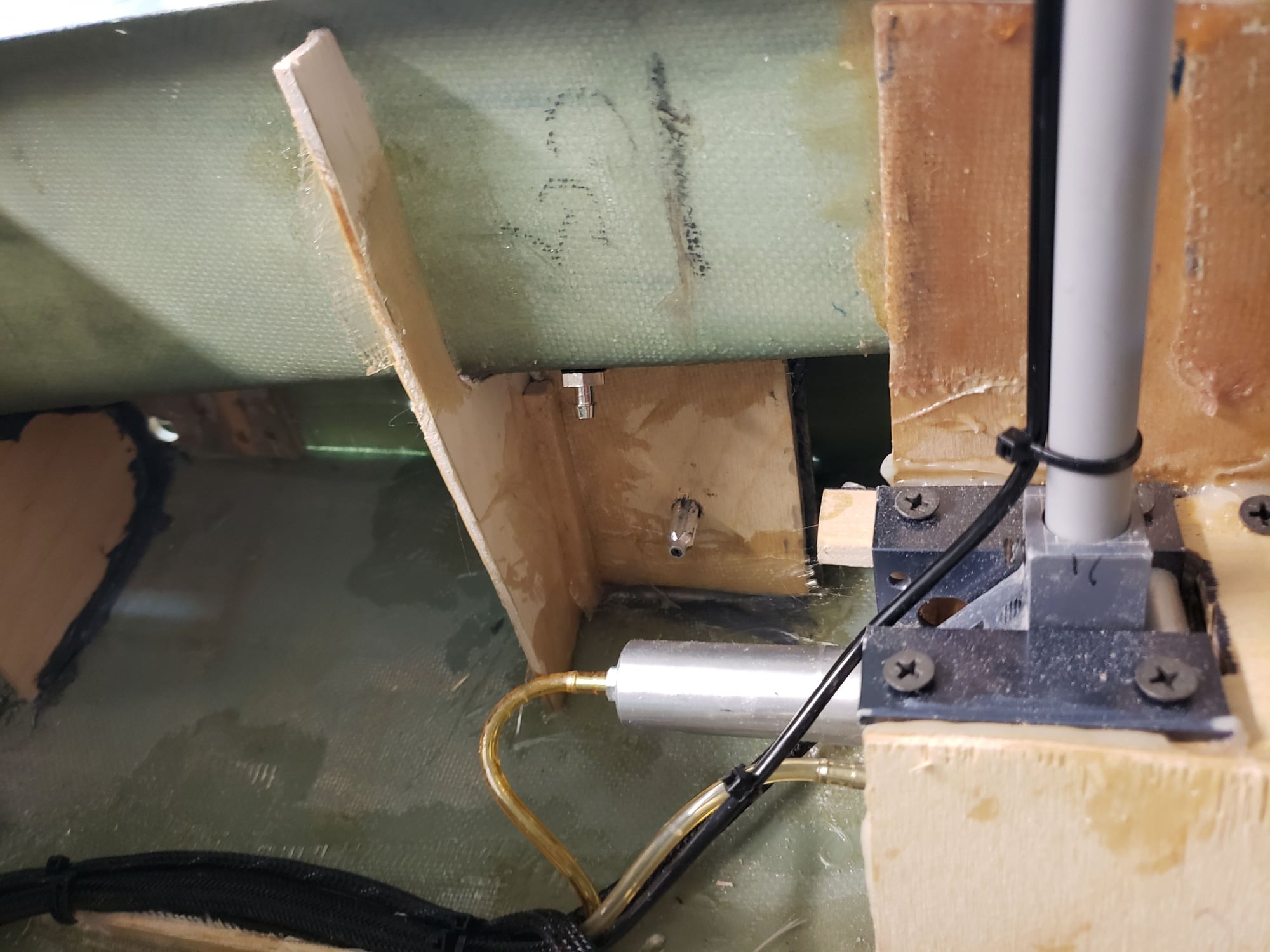
Built a 1/4 in ply box with 3/16 support former to hold the 10mm 2nd wing spar. Moveing foward.
Not to sure how I'm going to make the skin for the bottom yet so I can do door, or no doors. Haven't decided
Aluminum heat shield on the only part that will be close to the pipe, and radiates up. Made out of thin aluminum with 4mm wood spacers glued to top hatch
Fuel tanks were done a few days back Used 1/4in ply strips to build a frame around the new Dubro 80oz fuel tanks, I used plastic epoxy to help secure it to frame along with silicone, once I'm done on inside it will get set in with the 3 mounting points being glued for easy removal buy 3 screws
Built a 1/4 in ply box with 3/16 support former to hold the 10mm 2nd wing spar. Moveing foward.
Not to sure how I'm going to make the skin for the bottom yet so I can do door, or no doors. Haven't decided
12-03-2019, 07:28 PM
#140

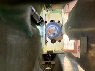
Just spent an HOUR removing one gear. Nightmare, with inaccessible nuts and a wheel collar. This thing was assembled outside, then glued in allowing for no service. That said, I have more respect for this gear’s strength than I did before. It’s well supported for a long distance. Just need the mounting blocks to be reinforced with carbon fiber and methylmethacrylite epoxy.
12-03-2019, 07:49 PM
#141
My Feedback: (34)
Just spent an HOUR removing one gear. Nightmare, with inaccessible nuts and a wheel collar. This thing was assembled outside, then glued in allowing for no service. That said, I have more respect for this gear’s strength than I did before. It’s well supported for a long distance. Just need the mounting blocks to be reinforced with carbon fiber and methylmethacrylite epoxy.
12-04-2019, 05:14 AM
#143
By the way, instead of silicon caulking, try Goop Glue and see if you like it. It sticks to inner fiberglass surfaces, and anything else, really well. Also, I was just playing around with the thrust tube and somehow it slipped inside the fuse. I may not be able to get it out again. I don't even have a hatch cut yet. Doh. I'll post pictures in a while.

 12-04-2019, 11:30 AM
#145
My Feedback: (34)
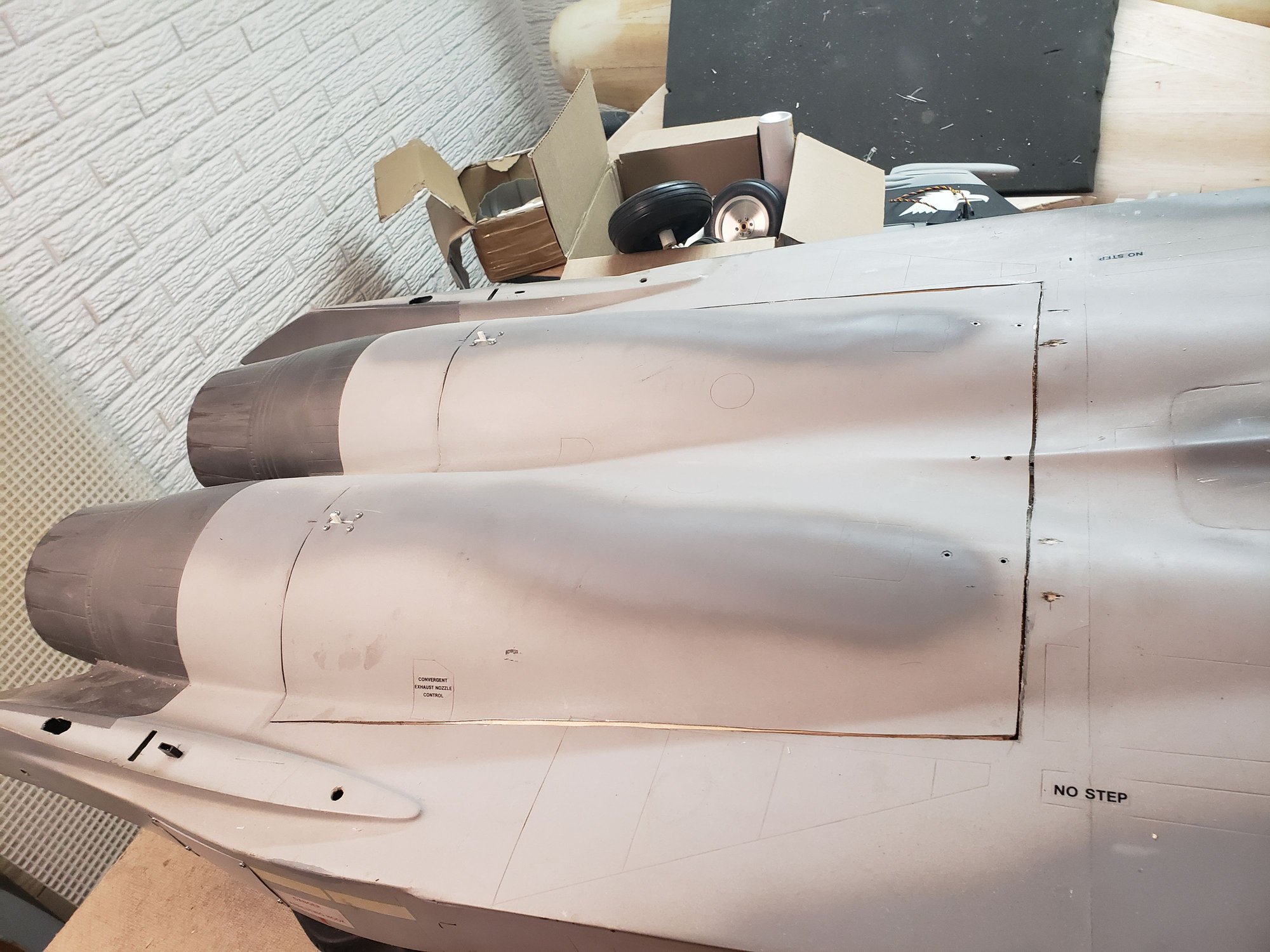
I would move the pipe forward a tad, Make the tail pipe flush or a tiny bit inside the fuse, I don't have a single just that the pip actually sits out like that. Pulse with the huge outlets we have there is still a good distance between pipe and jet, I will put a strip of super thin aluminum flashing held on by Goop or Silicone to hold in place incase I have a odd hot/fail start.
I will say, go to Lowes and get you a $20 can of polyester resin, Its funny, looking all over the can no were dose it say its polyester but it is as it requires a few drops of the clear catalyst to kick off. This stuff stinks compare to epoxy's. But I have adds fiberglass to all my wood formers like Byron did, (like the peace next to your bell mouth. It really helps and unlike epoxy, with a few extra drops, it can be pretty firm in a hour. The fiberglass cloth they sell at Lowes is good to.
I wish who ever cut my hatch would of taken more time, planned out the hatch with blue tape, then double checked measurement to ensure it was square as it would of looked better and made the hatch install a lot easier.
I think I'm done modifying the fuse, Will install the motor tonight so I can tuck away the wires, then finally install the fuel tank set up. Then its time to cut out the flaps, I have been tempted not to add them, but the weight is so little, and I remember needing them on my 1/9 F15 but it was so heavy for its size.
12-04-2019, 11:42 AM
#146
My Feedback: (34)
https://www.rcgroups.com/forums/showthread.php?2816053-Attention-Skymaster-F15-owners!-Scale-exhaust-nozzles!
I wish I could get some sweet 3d Printed Tail cones like these.
I wish I could get some sweet 3d Printed Tail cones like these.
12-04-2019, 11:46 AM
#147
https://www.rcgroups.com/forums/showthread.php?2816053-Attention-Skymaster-F15-owners!-Scale-exhaust-nozzles!
I wish I could get some sweet 3d Printed Tail cones like these.
I wish I could get some sweet 3d Printed Tail cones like these.
 12-06-2019, 05:00 PM
#150
My Feedback: (34)
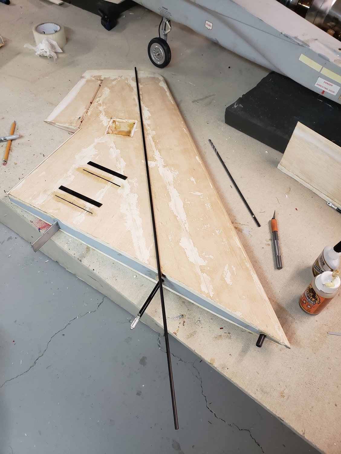
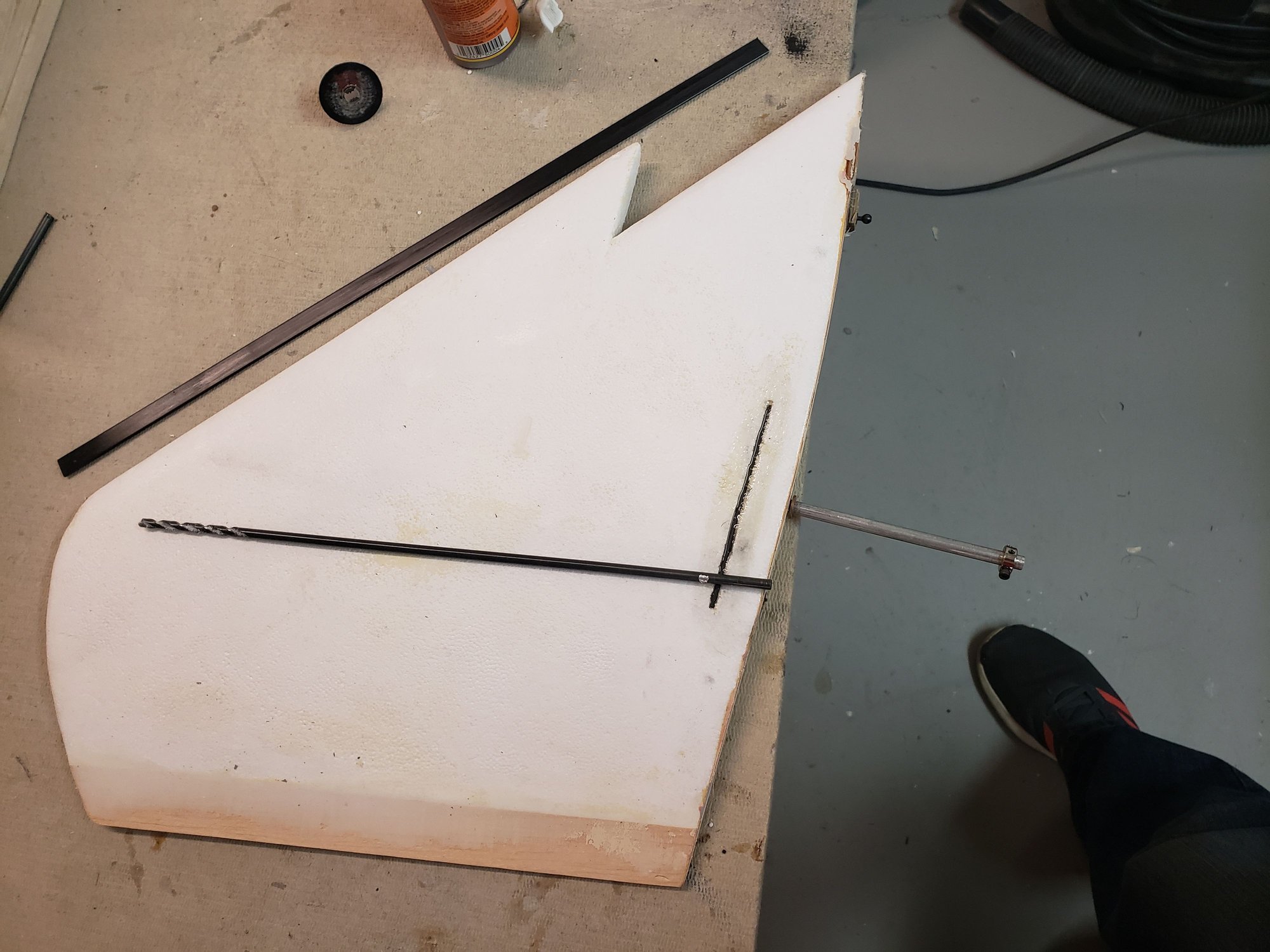
So used my drill bit to get holes for carbonfiber rods nice and straight, then put rod in drill, and drilled it all the way in.
Then cut channels in for carbonfiber flat peaces with groves cut in to cradle Aluminum in elevators and flat wing tub.
Cut flaps off, now time to shape them
Then cut channels in for carbonfiber flat peaces with groves cut in to cradle Aluminum in elevators and flat wing tub.
Cut flaps off, now time to shape them